1-wire interface overvoltage protection
I'm designing a robust 1-wire output for an IoT board.
The interface should be able to withstand high voltage. Mainly the same voltage level as the board power supply. That's 12V to 36V DC.
The protection is intended for the board only, not the devices connected to it.
Consider the protection must be able to withstand permanent voltage.
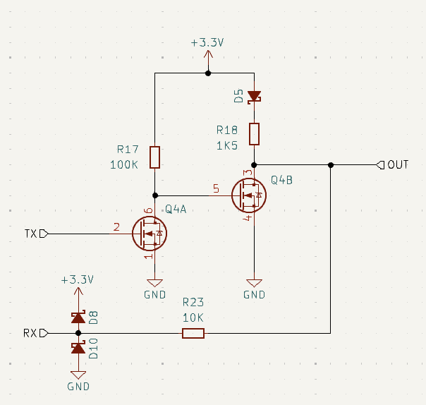
This is what I came up with.
I'm not going to use UART as TX and RX lines. I'll do it by software, I separated the direction because it's easier to provide a stronger protection. I'm not sure how to merge the two lines.
The OUT label is where the 1-wire goes out of the board. RX and TX are the two lines that go directly to microcontroller.
R18 is the 1-wire pullup.
D5 protects protects the 3.3V line from the high-voltage that might apply on the line.
Mosfet VDS should be able to withstand the high-voltage. The mosfet circuitry is used to overcome the high resistance of R23 when the microcontroller wants to transmit data to the line.
Will that work?
1 answer
It's been a while since I did 1-wire, so I don't remember the current levels. R18 seems rather high for supporting the minimum required voltage at the maximum possible current.
Let's say for sake of example that your 1-wire device is specified to work down to 2.0 V. You're already going to lose 300 mV or so thru D5. That leaves 3.0 V coming out of D5, so only allows 1 V drop across R18. With the value you have now, the maximum operating current the device can draw is (1 V)/(1.5 kΩ) = 667 µA. Are you sure your device can operate on that little?
Another issue to consider is the current that will be dumped on the 3.3 V supply when OUT is externally driven to 36 V. Right now that is around 3.2 mA thru R23. There is no problem as long as you are always draining at least that from the 3.3 V supply internally. Also consider if 36 V could be present with this device off. What would that do to the internal 3.3 V supply? A dedicated Zener clamp might be in order.
1 comment thread

1 comment thread