Post History
I'm designing a robust 1-wire output for an IoT board. The interface should be able to withstand high voltage. Mainly the same voltage level as the board power supply. That's 12V to 36V DC. The p...
#3: Post edited
by
 DeadMouse
·
2024-03-10T16:11:24Z (about 1 year ago)
DeadMouse
·
2024-03-10T16:11:24Z (about 1 year ago)
- I'm designing a robust 1-wire output for an IoT board.
- The interface should be able to withstand high voltage. Mainly the same voltage level as the board power supply. That's 12V to 36V DC.
- The protection is intended for the board only, not the devices connected to it.
- Consider the protection must be able to withstand permanent voltage.
- This is what I came up with.
- I'm not going to use UART as `TX` and `RX` lines. I'll do it by software, I separated the direction because it's easier to provide a stronger protection. I'm not sure how to merge the two lines.
- The `OUT` label is where the 1-wire goes out of the board. `RX` and `TX` are the two lines that go directly to microcontroller.
- R18 is the 1-wire pullup.
- D5 protects protects the 3.3V line from the high-voltage that might apply on the line.
- Mosfet VDS should be able to withstand the high-voltage. The mosfet circuitry is used to overcome the high resistance of R23 when the microcontroller wants to transmit data to the line.
- 
- I'm designing a robust 1-wire output for an IoT board.
- The interface should be able to withstand high voltage. Mainly the same voltage level as the board power supply. That's 12V to 36V DC.
- The protection is intended for the board only, not the devices connected to it.
- Consider the protection must be able to withstand permanent voltage.
- This is what I came up with.
- I'm not going to use UART as `TX` and `RX` lines. I'll do it by software, I separated the direction because it's easier to provide a stronger protection. I'm not sure how to merge the two lines.
- The `OUT` label is where the 1-wire goes out of the board. `RX` and `TX` are the two lines that go directly to microcontroller.
- R18 is the 1-wire pullup.
- D5 protects protects the 3.3V line from the high-voltage that might apply on the line.
- Mosfet VDS should be able to withstand the high-voltage. The mosfet circuitry is used to overcome the high resistance of R23 when the microcontroller wants to transmit data to the line.
- Will that work?
- 
#2: Post edited
by
DeadMouse
·
2024-03-10T16:09:05Z (about 1 year ago)
- I'm designing a robust 1-wire output for an IoT board.
- The interface should be able to withstand high voltage. Mainly the same voltage level as the board power supply. That's 12V to 36V DC.
- The protection is intended for the board only, not the devices connected to it.
- Consider the protection must be able to withstand permanent voltage.
- This is what I came up with.
- I'm not going to use UART as `TX` and `RX` lines. I'll do it by software, I separated the direction because it's easier to provide a stronger protection. I'm not sure how to merge the two lines.
- The `OUT` label is where the 1-wire goes out of the board. `RX` and `TX` are the two lines that go directly to microcontroller.
- R18 is the 1-wire pullup.
- Mosfet VDS should be able to withstand the high-voltage. The mosfet circuitry is used to overcome the high resistance of R23 when the microcontroller wants to transmit data to the line.
- 
- I'm designing a robust 1-wire output for an IoT board.
- The interface should be able to withstand high voltage. Mainly the same voltage level as the board power supply. That's 12V to 36V DC.
- The protection is intended for the board only, not the devices connected to it.
- Consider the protection must be able to withstand permanent voltage.
- This is what I came up with.
- I'm not going to use UART as `TX` and `RX` lines. I'll do it by software, I separated the direction because it's easier to provide a stronger protection. I'm not sure how to merge the two lines.
- The `OUT` label is where the 1-wire goes out of the board. `RX` and `TX` are the two lines that go directly to microcontroller.
- R18 is the 1-wire pullup.
- D5 protects protects the 3.3V line from the high-voltage that might apply on the line.
- Mosfet VDS should be able to withstand the high-voltage. The mosfet circuitry is used to overcome the high resistance of R23 when the microcontroller wants to transmit data to the line.
- 
#1: Initial revision
by
DeadMouse
·
2024-03-10T16:08:03Z (about 1 year ago)
1-wire interface overvoltage protection
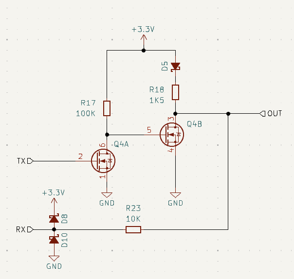
I'm designing a robust 1-wire output for an IoT board. The interface should be able to withstand high voltage. Mainly the same voltage level as the board power supply. That's 12V to 36V DC. The protection is intended for the board only, not the devices connected to it. Consider the protection must be able to withstand permanent voltage. This is what I came up with. I'm not going to use UART as `TX` and `RX` lines. I'll do it by software, I separated the direction because it's easier to provide a stronger protection. I'm not sure how to merge the two lines. The `OUT` label is where the 1-wire goes out of the board. `RX` and `TX` are the two lines that go directly to microcontroller. R18 is the 1-wire pullup. Mosfet VDS should be able to withstand the high-voltage. The mosfet circuitry is used to overcome the high resistance of R23 when the microcontroller wants to transmit data to the line. 