Post History
I am working with an IC that uses a partially intergrated regulated charge pump. The circuit looks like this: It behaves like a voltage doubler. However, when looking at other regulated charge p...
#1: Initial revision
by
 Mu3
·
2024-03-20T15:13:48Z (about 1 year ago)
Mu3
·
2024-03-20T15:13:48Z (about 1 year ago)
Regulated charge pump design
I am working with an IC that uses a partially intergrated regulated charge pump. The circuit looks like this: 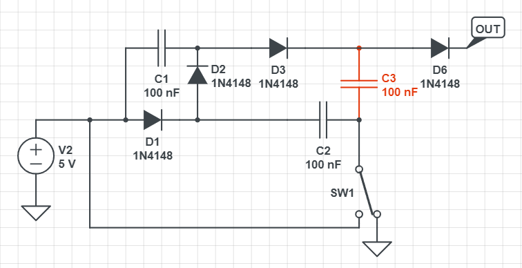 It behaves like a voltage doubler. However, when looking at other regulated charge pumps I am coming across much simpler designs such as this on for example: 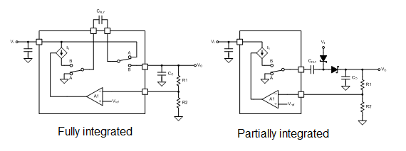 I understand the wokring of a single-stage charge pump and the fact that they can be chained together. However, the circuit from the first diagram confuses me as it looks like nothing I could find online. My questions are: - Why are C2 and C3 connected across D2 and D3? - What is the purpose of C1? - What type of charge pump is this?