Communities

Writing
Writing
Codidact Meta
Codidact Meta
The Great Outdoors
The Great Outdoors
Photography & Video
Photography & Video
Scientific Speculation
Cooking
Cooking
Electrical Engineering
Judaism
Judaism
Languages & Linguistics
Software Development
Mathematics
Mathematics
Christianity
Christianity
Code Golf
Code Golf
Music
Music
Physics
Physics
Linux Systems
Linux Systems
Power Users
Power Users
Tabletop RPGs
Tabletop RPGs
Community Proposals
Community Proposals
tag:snake search within a tag
answers:0 unanswered questions
user:xxxx search by author id
score:0.5 posts with 0.5+ score
"snake oil" exact phrase
votes:4 posts with 4+ votes
created:<1w created < 1 week ago
post_type:xxxx type of post
Search help
Notifications
Mark all as read See all your notifications »
Q&A

Comments on Filtering the high frequency noise in switching PSU

Post

Filtering the high frequency noise in switching PSU

+2
−2

It is well known that it is difficult to filter the noise generated by switching power supplies, and this difficulty increases as the PSU is supposed to deliver large currents.

For example, in a usual LC filter, the self may reach the saturation if a large current is passing through.

I would like to know what techniques are usually used in large current capable switching PSU to filter the (high frequency) output ripple.

To restrict the question:

  • I'm not interested in the 50Hz low frequency noise,

  • not interested in the EMI power line filtering,

  • not interested in proper use of ground planes, separation, minimizing area in current loops, not breaking current return paths, identifying high current flow paths and keeping them short and away from noise sensitive parts of the circuit and like.

  • I'm interested only in the output filter.


You still need to focus your question though.

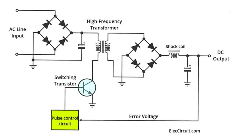
This basic circuit is more or less what I had in mind: switching

A part of the original question has already been answered. So, to focus on the remaining points, my question is now:

What can be done to reduce the common mode noise?

History
Why does this post require moderator attention?
You might want to add some details to your flag.
Why should this post be closed?

1 comment thread

General comments (13 comments)
General comments
Andy aka‭ wrote over 3 years ago · edited over 3 years ago

Are you talking about common mode noise that simultaneously affects both pos and neg output on the DC side (due to capacitive coupling in the transformer) or just differential noise i.e. conventional ripple artifacts? Both are treated differently and both these noise sources depend on different things in a design. Are we talking about DC-to-DC isolating converters or just plain ordinary buck/boost regulators?

Skipping 1 deleted comment.

Andy aka‭ wrote over 3 years ago

Can you adjust your question to more fully reflect your aim?

Skipping 1 deleted comment.

Andy aka‭ wrote over 3 years ago

I think you misunderstand it from the view of someone answering. Someone answering can make an answer aimed at a specific design and provide good information. Then, if I were answering, the way my brain seems to work is that I could sit back and think how this might be applied to similar (but not identical) designs. If you expect someone to brainstorm the full gambit of possible scenarios prior to making an answer then your expectations are too high.

Skipping 1 deleted comment.

Andy aka‭ wrote over 3 years ago

You still need to focus your question though. Asking for a schematic is also problematic because it just may not be the topology that is most appropriate to you. If I answered and you then said "yes but what about this or that converter" I'd have been wasting my time on the original answer. You have to be reasonable.

coquelicot‭ wrote over 3 years ago

@Andy. See my edit.

Andy aka‭ wrote over 3 years ago · edited over 3 years ago

The circuit you have posted will not have any significant degree of common mode noise because it is not an isolating DC-to-DC converter because the same GND symbol is used on either side of the transformer. This is so absolutely the reason why a circuit is needed. The circuit will only produce differential noise on the DC output. The devil, as always, is in the details.

Andy aka‭ wrote over 3 years ago

The circuit is still problematic. It isn't a conventional flyback converter (that require extensive CM filtering due to a lack of earth) because flybacks don't use a bridge rectifier. So maybe it's a forward converter that deal with higher power transfer (than flybacks) and usually have an incoming earth that can be used to make a decent CM filter work properly yet, the primary is driven by 1 transistor that is hardly ever used in forward converters because of higher power. It's still confusing.

Andy aka‭ wrote over 3 years ago · edited over 3 years ago

It also names the DC voltage as an error voltage and that is totally wrong. Like I said, the devil is in the detail and, in my humble opinion, if you want this question answering with respect to CM noise you need a believable circuit tied to a recognized power supply topology. The ElecCircuit.com picture doesn't fit this need.

coquelicot‭ wrote over 3 years ago

@Andy. This contradicts my experiments. Sure, in theory, you are right: ground is ground. But in my experiments on desktop computer ATX PSUs, I've observed that ground is a fiction. These PSU are so inherently noisy in the high frequency range that a common mode noise arrive SOMEHOW to the terminals (I'm not able to explain how). I was also able to test that whenever the ground has a huge self capacitance, it behaves much like a ground.

coquelicot‭ wrote over 3 years ago · edited over 3 years ago

@Andy. If you wish, you can do the following experiment: take an ordinary computer PSU and try to filter the noise at the output. You'll see. Regarding your other remarks, I will think about.

Andy aka‭ wrote over 3 years ago · edited over 3 years ago

Then we need a schematic of the actual power supply. This is exactly the problem behind answering your question - you are changing the goalposts and wasting time. I'm not going to do any physical experiments, after all? Why should I? Like I've said many times here: the devil is in the detail and you need to provide detail and stick with it and not suddenly evolve off into different power supplies. You won't get help from me on this question by doing what you're doing.

Andy aka‭ wrote over 3 years ago

Ground = fiction usually means poor o-scope probing.

coquelicot‭ wrote over 3 years ago

Sounds like I made everyone angry, by trying to improve things. What a mess! definitely too much for me, I leave.