Comments on High pass filter design
Parent
High pass filter design
Despite there are many filter calculators available on the web, I still have difficulties to translate what I need into calculator design parameters.
For my application, I need ideally a high pass filter that kill everything below 60Hz, and keep everything near 100Hz. More mathematically, I would like a HP filter that keep 99% of the signal (voltage) at 90 Hz, and kill x % of the signal at 60Hz (say x = 98%, but I can compromise to reduce the complexity of the filter).
Other considerations are:
- I don't care of phase distortion
- active filter is OK
- max amplitude of the signal +/- 8V
- very weak current (it is to be the input of an oamp).
How the real pros would translate these needs into design rules for a calculator?
Post
I saw this link by accident and, while Andy's and Olin's answers are spot on, I thought I'd expand a bit on the complications they describe, just so you know what you're missing (or meeting, should you decide to continue). Also, it might get a bit long, but that's why the voting system exists.
First, your requirements are quite tight, that is, you need a corner frequency of 90 Hz and a stopband frequency of 60 Hz. You also need some 100x attenuation of the signal, which means 40 dB stopband attenuation. You don't specifiy the corner attenuation, but let's assume you can live with the usual -3 dB, or better. That means you'll no longer have a flat(ter) passband, but that's not the problem: the order of the filter is directly proportional to the transition width.
Analog filters have 5 established classic approaches: Bessel(-Thompson), Butterworth, Chebyshev I & II, and elliptic (Cauer). There are many others, but these are known all over literature. Out of these, Bessel filters are somewhat special (they're meant to be used for a flat group delay, as opposed to frequency characteristics), so I'll not consider them. The other four would result in the following minimum orders to meet the requirements: 12 for Butterworth, 9 for Chebyshev I, and 6 for inverse Chebyshev (Chebyshev II) and elliptic, where I considered a 0.01 dB ripple for both Chebyshev I and elliptic, which would result in some 1.2 mV ripple, thus negligeable. If you can live with ~11.5 mV ripple, then 0.1 dB results in only a 5th order for elliptic (9th for Chebyshev I).
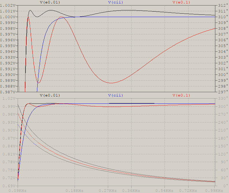
Let's assume N=6 for Chebyshev II and elliptic. Out of these two, Chebyshev II has a clear advantage over the elliptic due to the maximum flatness of the passband, but that means the 90 Hz corner frequency will be at -3 dB compared to the rest of the passband. To get a clearer picture, here's a zoom in the passband for elliptic with 0.01 and 0.1 dB ripple, and for Chebyshev II:
But all this is for an ideal case, a mathematical transfer function. This needs to be put in practice and, if an analog way is chosen, then you would need N/2 2nd order sections to build a filter. And this is where the problems appear:
-
You have to decide whether you need only one opamp per 2nd order section, or two, or three. This is not as simple as it may sound, because single opamp stages are limited in terms of quality factor and need special considerations for stage gain (additional dividers or even opamp attenuators might be needed). And if you do decide that you want single-opamp stages (and let's assume you can get around with only dividers), you'll find out that pole/zero stages that are closer to the corner frequency have higher Q that cannot be built, or will be too sensitive to component tolerances. Which means using at least two opamps per stage, thus 6 opamps in total. Let's say you have a quad opamp, that means two opamps. So far.
-
Then decide what tolerance your components will have (5% resistors? 1%, less?, capacitors?). You'll find out that you'll need quite a few passive elements per stage: at least two capacitors, and 5-6 and upwards resistors.
Even if "only" these two are the only ones that you have to take care of, the result will be a noise and thermal susceptible filter, that will no longer give you that clear mathematical frequency response. Not to mention you'll get a nice mini-PCB that you'll have to handle for proper signal routing.
And what what do you get at the end of these? This:
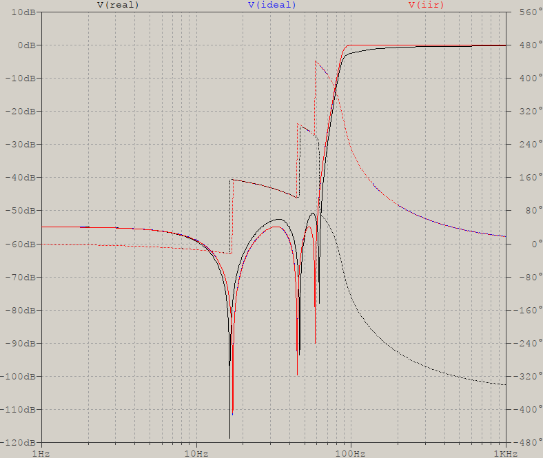
V(ideal) is the mathematical transfer function (truncated to float terms), V(real) is a quasi-real approach (1% resistors, 5% caps, ideal opamps -- these also contribute), and an IIR approach, V(iir), which almost overlaps with the ideal, due to roundings & co. The BOM (bill of materials): 7 resistors + 3 caps per 2nd order stage, 3 stages, where I have used a 2 opamp verion, CGIC (current generalized immitance converter). (I set the corner frequency to 100, instead of 90, by accident -- same thing)
So, if you can live with that, good luck, otherwise, as the others have said, re-thinking your strategy is the way to go.
To expand on the filter design would mean at least a thick book, so I'll thin it down to some bare necessities. I'll mention that there are all-pole filters (their lowpass prototype transfer function has a constant in the numerator: Bessel, Butterworth, Chebyshev I, Papoulis, Pascal, Legendre, etc) and pole-zero filters (the numerator has zeroes: elliptic, Chebyshev II or inverse Chebyshev, inverse Pascal, in fact all inverse filters); here we're dealing with the latter.
I'll use Octave to show the steps for the filter design, but I have my own scripts & co, i.e. there are numerical differences between what Octave will show and what I calculated, because of the differences in approaches. The methodology is what matters. There may be software around the Internet, Iowa Hills comes to mind, but most of the ones I know deal with IIR (digital) filters.
To determine the values, I used your requrements:
fp = 90;   # passband (corner) frequency
fs = 60;   # stopband frequency
delta_s = 1/99;  # attenuation
delta_p = 0.001; # arbitrary allowable passband ripple
Ap  = -20*log10(1 - delta_p);  # passband ripple, dB
As  = -20*log10(delta_s);      # stopband attenuation, dB
Asc = 3;         # attenuation @fp for all-pole filters, dB
Note that for all-pole filters I am using Asc for fp, and leave it to Ap for pole-zero filters (even if frequency scaling can adjust that). The exact values for the passband and stopband ripple are Ap=0.0086902 and As=39.913; even if I used rounded values in the answer above, the orders don't change.
To calculate the minimum order:
Nbutt  = buttord(fp, fs, Asc, As, 's');
Ncheb1 = cheb1ord(fp, fs, Ap, As, 's');
Ncheb2 = cheb2ord(fp, fs, Asc, As, 's');
Nellip = ellipord(fp, fs, Ap, As, 's');
Nellip2 = ellipord(fp, fs, 0.01, As, 's'); # for the 2nd elliptic case
There are 7 ways to design an elliptic filter, Octave does it differently than what I used before. I'll show how Octave does it, but I'll use the values as calculated before, to avoid reclaculating everything. So, calculate the poles, zeroes, and gain for the elliptic filter, but use normalized (unity) frequency to avoid large numbers (also use Ap=0.01 and As=40 to get the same numbers):
[z, p, g] = ellip(Nellip, 0.01, 40, 1, "high", 's');
With these you can make the transfer function but it will come out as an expanded version:
[num, den] = zp2tf(z, p, g);
tf(num, den)
                  0.9988 s^6 + 0.9 s^4 + 0.2146 s^2 + 0.008854
 y1:  --------------------------------------------------------------------
      s^6 + 2.691 s^5 + 4.551 s^4 + 5.075 s^3 + 4.193 s^2 + 2.2 s + 0.8854
If the transfer function is kept this way it will be made of 6th degree polynomials, which means that any small perturbance at the input will translate into a 6th power at the output. This is a cause for instablilites and overflow (for digital filters), so the usual step is to break it down into 2nd order sections. For this, since the poles are complex-conjugate, group them in pairs so that each section would look like this ($z_n$ = zeroes, $p_n$ = poles):
$$H_{2^{nd}}(s)=\frac{s^2+|z_n|^2}{s^2-2\Re(p_n)s+|p_n|^2}$$
With the inital values (for the reason mentioned above):
$$ H(s)=\frac{s^2+0.029502}{s^2+0.18934s+0.77767} \frac{s^2+0.2}{s^2+0.79928s+0.96608} \frac{s^2+0.34054}{s^2+2.1379s+1.4822} $$
I've chosen the modified CGIC for this, which has the basic topology like this:
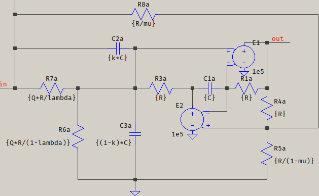
and if $\mu=2\lambda$ its transfer function is reduced to this:
$$H(s)=(2\kappa-\mu)\frac{s^2+\frac{1}{\left(\frac{2\kappa}{\mu}-1\right)R^2C^2}}{s^2+\frac{1}{QRC}s+\frac{1}{R^2C^2}}$$
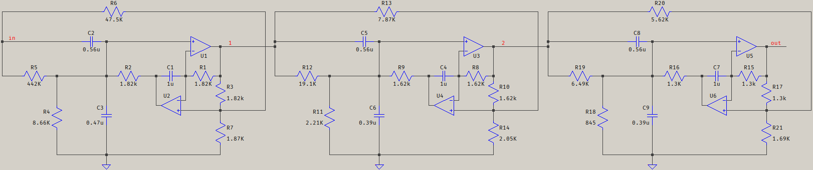
Since this resembles the transfer function of the 2nd order stages above, a system of equations is formed to solve the values of the elements, with C imposed. The results are scaled upwards from the unity frequency that was used, and the result is this:
For the IIR omit 's' in the ellip() function above. I used a 8192 Hz sampling frequency (quite large, a whim). Implementation is more involved, though, it requires some sort of DSP, with ADC/DAC, proper pre-/post-filtering, etc. For a case of "a simple measuring" it might not be worth it.
I will end by reinforcing what the other answers hinted at: that what you want and what you need are two different things, so even if this answer deals with the filter design, it doesn't change the underlying X-Y problem.

1 comment thread