Comments on Using FET based followers and design rules
Parent
Using FET based followers and design rules
Usually, voltage followers are built with bipolar transistors (or with opamps if better precision is needed). In this case, the simple rule says that the transistor emitter "follows" the input voltage one diode drop below, a somewhat approximate but understandable term.
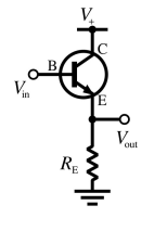
It is perhaps less usual to see field effect based followers, and I'm particularly interested in jfets and mosfets.
From my readings about this topic, it is still unclear to me how to determine the voltage drop introduced by these transistors (parallel to the diode drop for the bipolar transistor follower).
Also, if there is a way to control this drop (without using an opamp), what are the design rules, or perhaps the rules of thumbs ?
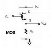
Allow me to address the MOSFET only as a source follower. - this has very unpredictable linear use without voltage …
4y ago
"Also, if there is a way to control this drop (without using an oamp), what are the design rules, or perhaps the rules o …
4y ago
FET source-followers are generally less predictable than BJT (bipolar junction transistor, like NPN or PNP) emitter-foll …
4y ago
> ... it is still unclear to me how to determine the voltage drop introduced by these transistors... Very interesting …
4y ago
In addition to Olin's answer: > and I'm particularly interested in jfets and mosfets. If you decide to go dow …
4y ago
Post
FET source-followers are generally less predictable than BJT (bipolar junction transistor, like NPN or PNP) emitter-followers.
An emitter follower output is one diode drop below the input. The voltage across a diode varies little as a function of the current, so this offset remains fairly constant. The absolute voltage across this diode is also reasonably predictable.
The input to output drop of a FET source-follower is whatever gate voltage is required to pass the source current. The absolute value of that voltage is less well specified than the drop on a silicon diode.
Take a look at gate threshold voltage specifications for some common FETs. I just looked up the IRLML2502 as an example of a low voltage FET meant to be driven with logic level gate voltages. Even this FET is specified for a gate threshold voltage anywhere from 600 mV to 1.2 V, and that's just at 250 µA.
Take a look at the typical characteristics of what gate voltage is required to sustain what collector current:
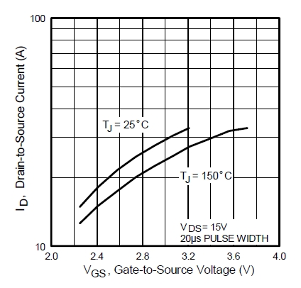
First, notice how little this graph really tells you. It only shows currents from around 15 mA to a bit over 30 mA. It's not of much help if your current is only, 2 mA, for example.
Second, notice the rather large change in gate voltage to get different channel currents. Even at the single fixed temperature of 25 °C, it takes 2.5 V to get 20 mA, and over 3 V to get 30 mA. At 150 °C it takes over 3.4 V to get the same 20 mA.
Another characteristic to consider is the how much D-S voltage is needed before it no longer matters much:

It takes about 1 V or so at 15 mA, and over 2 V at higher currents. Contrast that to a BJT where this is well under 1 V except at quite high currents for the device.
So even for this one example low voltage FET, the G-S voltage varies much more than the B-E voltage of a BJT, and more D-S voltage is required before that stops being much of a dependency. These characteristics are even worse for higher voltage FETs which are usually intended to operate with a 10 V or so gate range.
All around, This means that the G-S voltage of a FET is less predictable to start with, and will vary more, than the B-E voltage of a BJT in similar conditions. Since all the G-S or B-E voltage variations show up directly on the output of follower circuits, FETs simply don't make as good followers as BJTs do.
do you see any reason to use a FET follower?
A FET follower can be used when the larger and less certain delta from input to output voltage is acceptable.
One advantage of a FET follower is very high input impedance, and that is independent of the current being delivered to the load. That means FET followers have much higher current gain than BJT followers.
But a current gain of (practically) zero at DC (only the leakage current (on the order of 1 pA) is flowing(?)?
The current gain is the output current divided by the input current. For a BJT follower, that is Iemitter/Ibase = β+1. For a FET follower, it is Isource/Igate. Since the gate current is only leakage, the current gain of a FET follower is very high for anything more than tiny output currents.
As was pointed out in a comment, "current gain" doesn't really make sense when the output current isn't some reasonable function of the input current. That is not the case with a FET follower. I was only trying to point out that the input of a FET follower has high impedance. Essentially no current (just leakage) is drawn from the source signal, although that signal controls substantial output current. This is in contrast to a BJT follower where the output current is reasonably proportional to the input current, and the ratio is gain+1 of the transistor.

1 comment thread