Comments on Understanding the s11 and s21 coefficients of a microstrip line with resistor to ground
Parent
Understanding the s11 and s21 coefficients of a microstrip line with resistor to ground
I thought I understood the theory of scattering parameters, smith charts etc. until I tried a practical example.
The following stupid example is supposed to be a microstrip line shunted by two 100 Ohm resistors to ground, that is, an equivalent resistance of 50 Ohm (also checked at DC with a voltmeter).
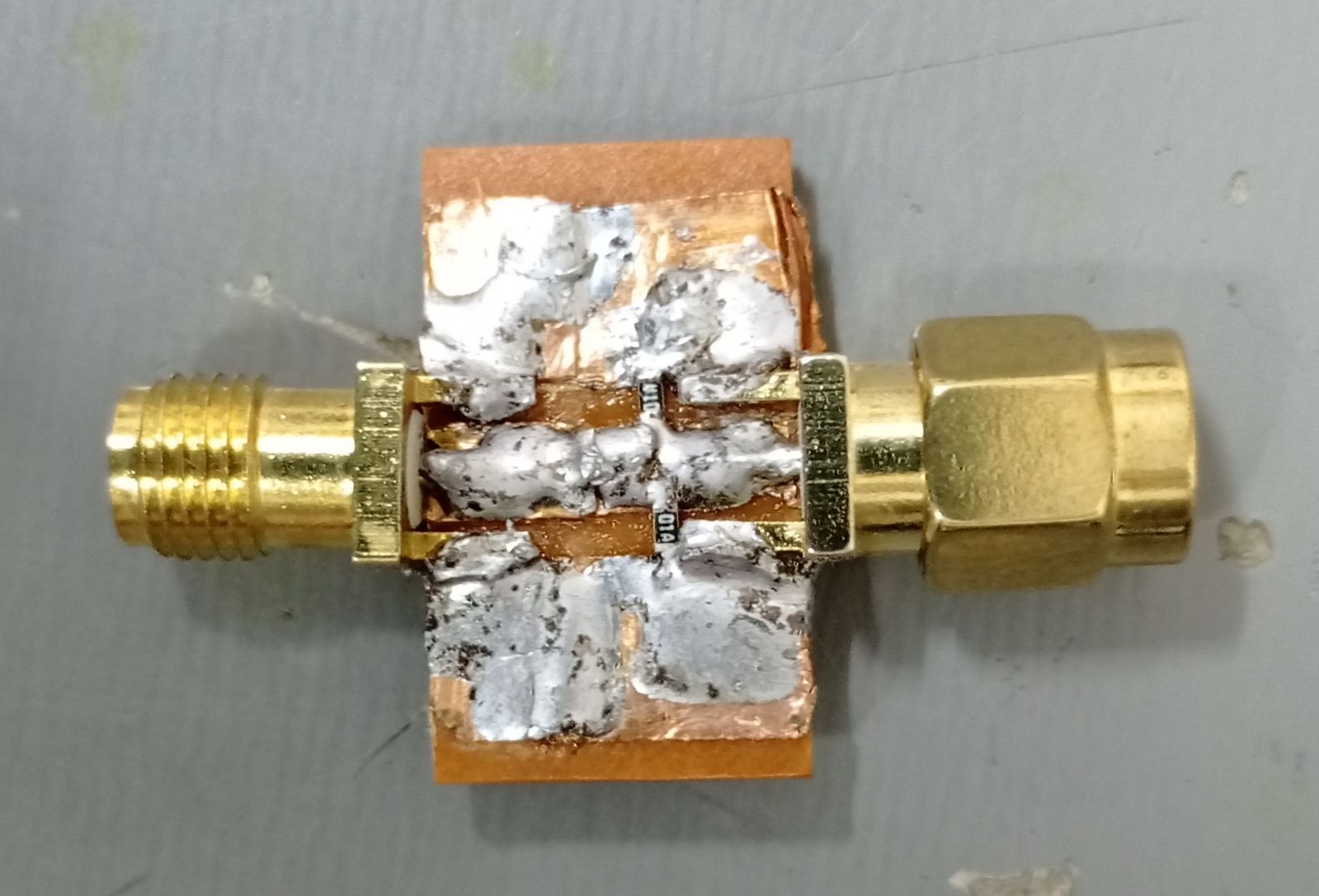
Note: the bottom of the plate is copper plated.
Now, I cannot afford a good network analyzer, so I bought a nanoVNA network analyzer (image below). Admittedly, this is a toy, but it is a well regarded toy, especially for frequencies below 300MHz. So, I assume it gives not so bad results for this experiment.
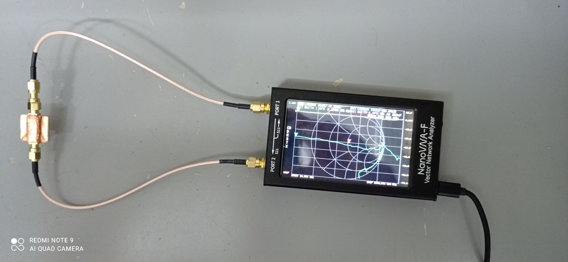
Note: the analyzer has been calibrated.
Testing the example above, here are the results returned by the nanoVNA:

Now, -9 dB is equivalent to a ratio of 0.34 approximately, and -3.53 db is equivalent to a ratio of 0.66 approximately. I expected S11 to be near 0. Regarding s21, I didn't know exactly what to expect.
Notice that these measurements begin at 10 kHz, where everything should behave like the theory, due to the very low frequency.
Trying to understand these values, I finally found an excellent article, full of practical data.
Now, according to fig. 1, it seems that the stimulus has an output impedance of 50 ohm. This is my first question:
Question 1: Should we assume that network analyzers are built in such a way the stimulus (signal toward the port) has an output impedance of 50 ohm?
Question 2: How to understand the above results ?
Post
In the absence of VNA product documentation......
Now, -9 dB is equivalent to a ratio of 0.34 approximately, and -3.53 db is equivalent to a ratio of 0.66 approximately. I expected S11 to be near 0.
A 9 dB return loss is a reflection coefficient of $\pm$0.355. Accounting for slight discrepancies in the measurement, I suspect that the reflection coefficient ($\Gamma$) might in fact be -0.3333 (somewhere between 9 dB and 10 dB of return loss). And, a $\Gamma$ of -0.3333 would be obtained from a 25 Ω resistor relative to a measurement reference of 50 Ω: -
$$\Gamma = \dfrac{R_x- 50}{R_x + 50}$$
Plugging 25 Ω into $R_x$ means $\Gamma$ is -0.3333 and return loss is $-20 log_{10}{|\Gamma|}\text{ dB}$ = -9.54 dB.
So, why 25 Ω? It's the input impedance of the VNA in parallel with two 100 Ω resistors in parallel inside the soldered blob i.e. 25 Ω.
Regarding s21, I didn't know exactly what to expect.
If you used a straight cable with no 100 Ω resistors fitted then I would expect 0 dB but, now that the power is shared between the two parallel 100 Ω resistors and the input of the VNA, the signal power level measured by the VNA is half or -3.01 dB. OK the cable and other errors makes this -3.53 dB.

1 comment thread