Comments on How to plot the I-V curve of a tunnel diode?
Parent
How to plot the I-V curve of a tunnel diode?
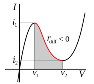
I am trying to understand tunnel diodes by experimenting with them. Research tells me they can have negative resistance, and can be used to build a high frequency oscillator. Tunnel diodes are supposed to have this I/V characteristic:
I don't really understand negative resistance, so I thought plotting the I-V characteristics myself would help me understand. Unfortunately, that didn't work.
What I did:
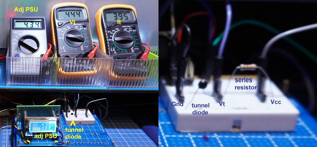
- Connect PSU in series with a protective, current limiting resistor, and the tunnel diode.
- Increase/decrease voltage level, in steps as fine as mV, and measure corresponding current values, as fine as 100 µA.
- Record each point on a graph of current as a function of voltage.
Here is my test setup:
As I increase voltage from 0 to IpeakV, the current increases as expected. Once approaching the IpeakV, the current suddenly jumped from tens of µA to some 400/500 mA. In other words, I just missed the most important measurements, those of the negative resistance region.
Why can I not measure the current as soon as the gradually increasing voltage V enters the negative region? How can I tell the tunnel diode not to "skip" the tunnel?
Post
Apparently you want to measure the current/voltage relationship of a tunnel diode. The tricky part is that the voltage isn't unique for currents over parts of the range. From your question:
Note that the current is still unique as a function of voltage. One solution is therefore to sweep the voltage and measure the current.
This needs to be done carefully, since small changes in the voltage can result in large changes in the current. You also need the voltage source to be very stiff (low impedance) so that the wildly changing current drawn by the device doesn't cause control instability.
One way to achieve this is with high open loop gain and negative feedback. If you are only feeding back the output voltage, and the control signal to drive the pass element is reasonably insensitive to the resulting current, then the system will be stable.
I haven't done this, but I'd probably start with an opamp driving an emitter follower, where the emitter voltage is fed back and is therefore ultimately what is regulated. The opamp output drives the base. The base voltage won't need to change much, even with large changes in the load current.
You might also want to add some current limiting so that you don't fry the device under test when the voltage goes a little too high. This limit needs to be above I1 in your diagram.
Another approach is to put a resistor in parallel with the diode under test. Make the resistor small enough so that the combined diode+resistor exhibits positive I/V slope over its whole operating range. You measure the I/V characteristics of the combined device, then do the math on the result to deduce the I/V characteristics of just the diode. This approach will require good accuracy, since the resistor is essentially adding noise to the desired signal. You still need to have sufficiently accuracy left after subtracting off the known "noise" signal.

1 comment thread