Communities

Writing
Writing
Codidact Meta
Codidact Meta
The Great Outdoors
The Great Outdoors
Photography & Video
Photography & Video
Scientific Speculation
Cooking
Cooking
Electrical Engineering
Judaism
Judaism
Languages & Linguistics
Software Development
Mathematics
Mathematics
Christianity
Christianity
Code Golf
Code Golf
Music
Music
Physics
Physics
Linux Systems
Linux Systems
Power Users
Power Users
Tabletop RPGs
Tabletop RPGs
Community Proposals
Community Proposals
tag:snake search within a tag
answers:0 unanswered questions
user:xxxx search by author id
score:0.5 posts with 0.5+ score
"snake oil" exact phrase
votes:4 posts with 4+ votes
created:<1w created < 1 week ago
post_type:xxxx type of post
Search help
Notifications
Mark all as read See all your notifications »
Q&A

Comments on How to plot the I-V curve of a tunnel diode?

Parent

How to plot the I-V curve of a tunnel diode?

+3
−1

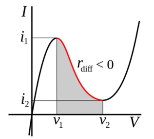
I am trying to understand tunnel diodes by experimenting with them. Research tells me they can have negative resistance, and can be used to build a high frequency oscillator. Tunnel diodes are supposed to have this I/V characteristic:

Image

I don't really understand negative resistance, so I thought plotting the I-V characteristics myself would help me understand. Unfortunately, that didn't work.

What I did:

  • Connect PSU in series with a protective, current limiting resistor, and the tunnel diode.
  • Increase/decrease voltage level, in steps as fine as mV, and measure corresponding current values, as fine as 100 µA.
  • Record each point on a graph of current as a function of voltage.

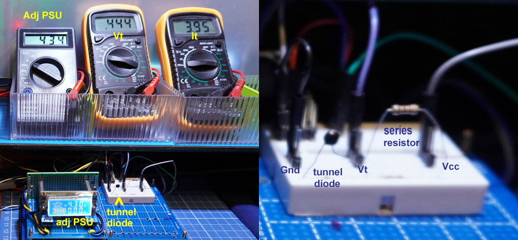
Here is my test setup:

Test setup

As I increase voltage from 0 to IpeakV, the current increases as expected. Once approaching the IpeakV, the current suddenly jumped from tens of µA to some 400/500 mA. In other words, I just missed the most important measurements, those of the negative resistance region.

Why can I not measure the current as soon as the gradually increasing voltage V enters the negative region? How can I tell the tunnel diode not to "skip" the tunnel?

History
Why does this post require moderator attention?
You might want to add some details to your flag.
Why should this post be closed?

1 comment thread

General comments (3 comments)
Post
+3
−0

Don't put the "protective" series resistor: connect directly your regulated power supply to the diode (with a short wire) and measure the current: the voltage regulator is all what you need to protect the diode and ensures you are not missing the negative resistance part. Then you increase very slowly the voltage until the curve is completed.

I once traced the VI curve of a a Gunn diode that way, with a stupid LM317 regulator. The only difference is that the Gunn diode has a higher voltage graph.

But since you say you have a well regulated power supply that allows fine tuning from 0V to 5V (at least), there should be no problem.

Otherwise, it is also easy to build an adjustable regulator for low voltages by driving a rail to rail opamp follower with a pot. This is sufficient for this task, since only few tens of mA are needed.


Now only the milliammeter resistance can create a problem.

Not a problem at all if your power supply has an integrated ammeter. But even without that, it is unlikely that the few tens of millivolts drop from the milliammeter would cause instability and missing the negative resistance part of the diode. Of course, the voltage should be measured at the terminals of the diode, and not after the milliammeter!

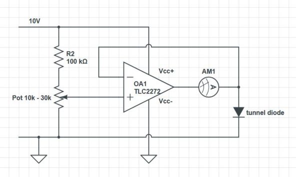
OR, with the pot-follower solution above, here is the schematic: tunnel-diode-setup

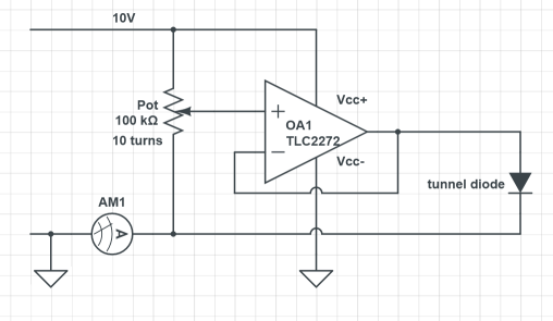
The voltage is measured at the terminals of the diode with the multimeter.


I'd break the pot up into a fixed resistor for the top part, and a pot to only allow up to a volt or so max for the bottom part. That reduces the settings that might cause damage, in addition to giving you higher adjustment resolution

In other words:

tunnel_3

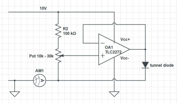
Yes, of course. My circuit was just "quick and dirty", but if it has to be used several times, it should be made safe as suggested by Olin.

Circuit Fantasist has also suggested the following:

tunnel_4

This should work as well, despite I somewhat dislike the idea to add inductance inside the control loop (due to the terminals of the ammeter, or worse, due to the ammeter itself if an analog ammeter is used), near a negative resistance.

History
Why does this post require moderator attention?
You might want to add some details to your flag.

1 comment thread

General comments (8 comments)
General comments
Circuit fantasist‭ wrote over 3 years ago

Simple and clear explanation... Now only the milliammeter resistance can create a problem. If only we can hide it somehow...

Skipping 1 deleted comment.

Circuit fantasist‭ wrote over 3 years ago

A good answer to my comment above… and demonstration of creative thinking… but there is another problem. If "the voltage is measured at the terminals of the diode with the multimeter", and the voltmeter is not perfect, it will divert a part of the current through the diode… and an error will appear. It would be more significant if the element under test has high resistance. This is another challenge to your ingenuity:)

coquelicot‭ wrote over 3 years ago · edited over 3 years ago

@Circuit fantasist. The most banal 3$ digital multimeters like the ones in the OP question have at least 1M ohm input impedance, more for more expensive voltmeters. So, this is pointless.

Olin Lathrop‭ wrote over 3 years ago

Good circuit, +1. However, I'd break the pot up into a fixed resistor for the top part, and a pot to only allow up to a volt or so max for the bottom part. That reduces the settings that might cause damage, in addition to giving you higher adjustment resolution. With 100 kOhm fixed and a 10 kOhm pot, you get about the same resolution from a 1-turn pot than you get with the 10-turn full-range pot.

Circuit fantasist‭ wrote over 3 years ago · edited over 3 years ago

Another suggestion - put the ammeter into the feedback loop (between the op-amp output and the common node where the inverting input and diode are connected). There are two benefits of this trick: first, the op-amp will raise its output voltage to compensate the ammeter resistance; second, both the diode and voltmeter (ADC) will be grounded.

Circuit fantasist‭ wrote over 3 years ago · edited over 3 years ago

... Of course, the ammeter will be floating. So in this solution either the voltmeter or ammeter are floating... but still there is a solution in which both are grounded.

Circuit fantasist‭ wrote over 3 years ago · edited over 3 years ago

@coquelicot‭, nice circuit diagram... Do you realize this is the well-known non-inverting configuration where TD is R1 and AM2 is R2? Or, this is the well-known "non-inverting current source" where TD is a "functional voltage-to-current converter" and AM2 is a "current-to-movement converter" (analog ammeter)...

Circuit fantasist‭ wrote over 3 years ago · edited over 3 years ago

I should make a "little" correction to one of my comments above. Connecting a voltmeter in parallel to the diode will not introduce an error because the voltage across it is produced by a voltage source. Rather this will be a problem in the case when the diode is driven by a current source (the dual setup for investigating S-shaped NDR).