Communities

Writing
Writing
Codidact Meta
Codidact Meta
The Great Outdoors
The Great Outdoors
Photography & Video
Photography & Video
Scientific Speculation
Cooking
Cooking
Electrical Engineering
Judaism
Judaism
Languages & Linguistics
Software Development
Mathematics
Mathematics
Christianity
Christianity
Code Golf
Code Golf
Music
Music
Physics
Physics
Linux Systems
Linux Systems
Power Users
Power Users
Tabletop RPGs
Tabletop RPGs
Community Proposals
Community Proposals
tag:snake search within a tag
answers:0 unanswered questions
user:xxxx search by author id
score:0.5 posts with 0.5+ score
"snake oil" exact phrase
votes:4 posts with 4+ votes
created:<1w created < 1 week ago
post_type:xxxx type of post
Search help
Notifications
Mark all as read See all your notifications »
Q&A

Comments on Filter RF Harmonics With Additional PI Network

Parent

Filter RF Harmonics With Additional PI Network

+2
−0

I have a 900MHz radio with a reference design matching network. The radio feeds to a PCB antenna (PCB antenna hasn't been verified with a VNA, and may not be a great match; this is a project to now fix this system).

There are over the limit harmonics from the 6th harmonic (~5,400MHZ) to (~8,100MHz).

The trace width of the antenna feed are (ostensibly) 50 ohms based on the board stackup.

After the reference design matching network, we did put down an empty PI filter so I can add some additional filtering.

Since we are trying to keep the impedance matched to 50 ohms, what is the best strategy to approach this circuit?

Do you start with a low pass filter and then tweak the low pass filter to re-match as best as possible to 50 ohms?

History
Why does this post require moderator attention?
You might want to add some details to your flag.
Why should this post be closed?

1 comment thread

General comments (7 comments)
Post
+4
−0

Since we are trying to keep the impedance matched to 50 ohms, what is the best strategy to approach this circuit?

A low pass $\pi$ network seems a good route to go. Basically your $\pi$ network is designed to do two important things: -

  • Impedance match a 50 Ω source to a 50 Ω load
  • Provide significant attenuation above 900 MHz for the reduction of harmonics.

The example below matches to 300 Ω but, the calculator allows you to enter both ends as 50 Ω: -

Low pass pi matching

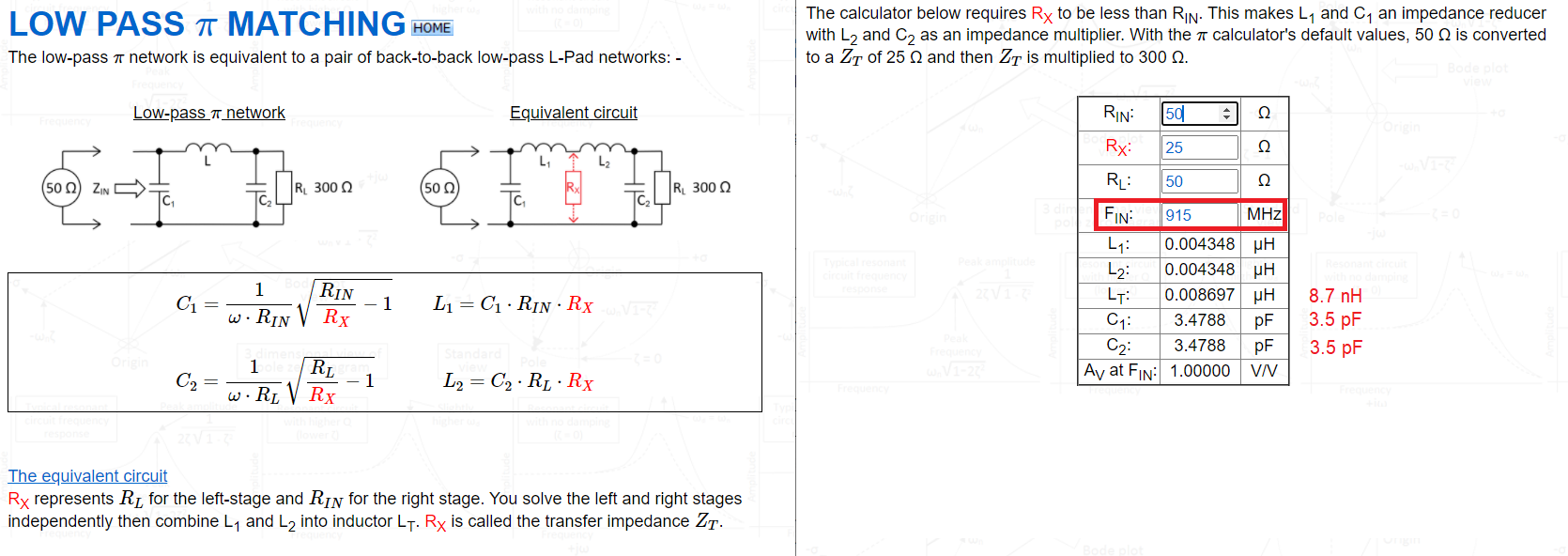
Picture and calculator can be found here.

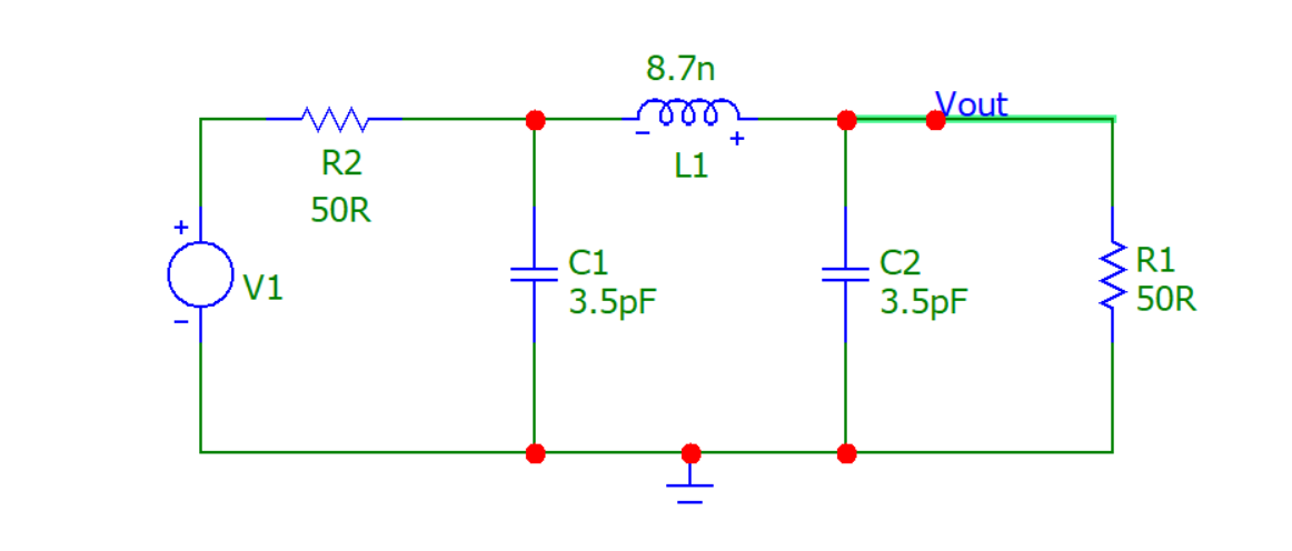
So, plugging the numbers into a simulator we get this circuit: -

simple low pass pi filter

And we get this AC response: -

simple low pass pi filter response

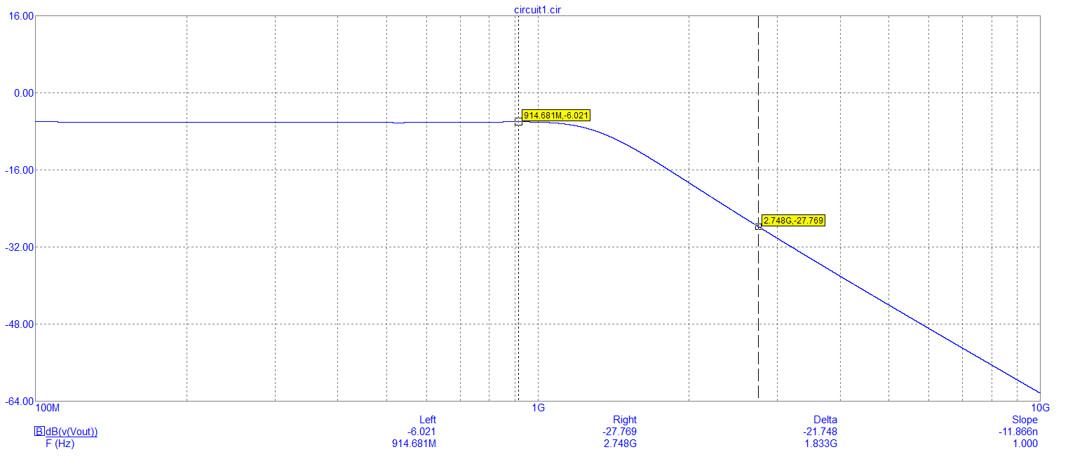
So, at 915 MHz we get the usual -6.021 dB input to output attenuation when you have matching input and output resistors (50 Ω) and, at the 3rd harmonic of 915 MHz we see an attenuation of 27.7 dB or, a relative attenuation of about 21.5 dB. Clearly that is very significant and, it's going to be even better at the sixth harmonic (around 40 dB I estimate).

But, remember, that at these frequencies, it's easy to get harmonic leakage to the output with badly chosen inductors and capacitors that are unsuitable for this application so, choose with care. Layout with care also.

If you need steeper roll-off above 915 MHz then the beauty about the $\pi$ network is that they can be cascaded (because they are impedance matching networks and interactions are minimal). So, here's a five stage example of a $\pi$ network schematic (operating at 10 MHz): -

PI cascaded

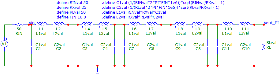
And here's the frequency response: -

PI cascaded simulation

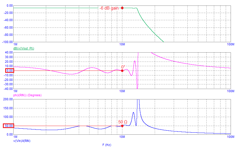
It's got perfect 50 Ω input and output impedance at 10 MHz and has rolled-off the 2nd harmonic (20 MHz) by around 70 dB.

History
Why does this post require moderator attention?
You might want to add some details to your flag.

1 comment thread

General comments (14 comments)
General comments
Lundin‭ wrote about 3 years ago

What's the reason you'd pick a PI low pass over a Chebyshev one? I thought Chebyshev were ideal since they give a much steeper dip after carrier?

Andy aka‭ wrote about 3 years ago · edited about 3 years ago

@Lundin if the simpler pi filter provides enough attenuation then no need to go to a more sophisticated filter. However, you can absolutely stack end-to-end pi filters to get both impedance matching and steeper roll-off.....

Andy aka‭ wrote about 3 years ago

... If you look at the link to the calculator in my answer and scroll down I've made a 5 stage filter and that has a monstrous and slope here.

Lundin‭ wrote about 3 years ago

Just curious since my experience (I'm definitely not a RF designer) is that PI filters are mostly used for general EMC, like when you need to block emissions over a very broad frequency range. But harmonics are specific and you know where they will be at, so why not just get rid of them.

Lundin‭ wrote about 3 years ago

In this case it is LoRa, which is supposed to use spread spectrum to compensate for high output power, so I don't get why the harmonics are that prominent. It's max 14dBm carrier if I remember correctly.

Andy aka‭ wrote about 3 years ago

@Lundin a PI filter is the archetypal impedance matching network to turn to. The fact that it can have seriously good attenuation characteristics outside the pass band is a major bonus. Usage of PI filters in reduction of EMC isn't really using them as a proper (intended) circuit but just as a bidirectional filter. They are still called PI filters but they are really just a simple method of making a bidirectional filter.

Andy aka‭ wrote about 3 years ago

@Lundin trying to target a specific frequency with a notch filter is haphazard and relies on low drift components. Having said that, you can add a capacitor across the inductor in the PI filter and get an elliptic (Cauer) filter that does do that (but at the expense of not being great if the bandwidth of unwanted frequencies is wide)

Andy aka‭ wrote about 3 years ago

Regards LoRa, I can't answer that so maybe address it to the OP.

leroy105‭ wrote about 3 years ago

@Andy Aka -- I got the hardware in hand and implemented a Chebyshev using the PI network in front of the reference stack of matching components and filtering. 0.2dBm drop at the fundamental of 915MHz & 12 dB drop at the most severe 7GHz harmonic. That's going to be darn close to passing FCC limits once we remeasure.

leroy105‭ wrote about 3 years ago · edited about 3 years ago

@Lundin - I've worked on a number of LoRa systems we have seen all kinds of over-limit harmonics in the past (never been tasked to filter one). LoRa transmit is usually 20+dBm + antenna gain, so you can get some pretty honking regulatory readings on the spurious emissions side.

leroy105‭ wrote about 3 years ago

@Andy, I didn't get a perfect response from the filter calculator I used. Do you think that is most likely due to a not-perfect 50 ohm match on the board, so the filter calculations are off a bit?

Andy aka‭ wrote about 3 years ago

You didn't say what calculator you used or what values it came up with.

leroy105‭ wrote about 3 years ago

C1 - 3.6pF, L1, 10nH, C2, 3.6pF -- was what the calculator I used said [really similar to your values]. I tweaked the capacitance and inductance bit in two other test runs and in both cases +0.4dB (in the wrong direction!). You could make a week long science experiment and do a bunch of iteration testing but I think we fundamentally have as good as the low Q componets I have on hand can do.

Andy aka‭ wrote about 3 years ago · edited about 3 years ago

Yeah I think the 10 nH is a tad high compared to the real true value needed (8.7 nH)