Filter RF Harmonics With Additional PI Network
I have a 900MHz radio with a reference design matching network. The radio feeds to a PCB antenna (PCB antenna hasn't been verified with a VNA, and may not be a great match; this is a project to now fix this system).
There are over the limit harmonics from the 6th harmonic (~5,400MHZ) to (~8,100MHz).
The trace width of the antenna feed are (ostensibly) 50 ohms based on the board stackup.
After the reference design matching network, we did put down an empty PI filter so I can add some additional filtering.
Since we are trying to keep the impedance matched to 50 ohms, what is the best strategy to approach this circuit?
Do you start with a low pass filter and then tweak the low pass filter to re-match as best as possible to 50 ohms?
2 answers
Since we are trying to keep the impedance matched to 50 ohms, what is the best strategy to approach this circuit?
A low pass
- Impedance match a 50 Ω source to a 50 Ω load
- Provide significant attenuation above 900 MHz for the reduction of harmonics.
The example below matches to 300 Ω but, the calculator allows you to enter both ends as 50 Ω: -
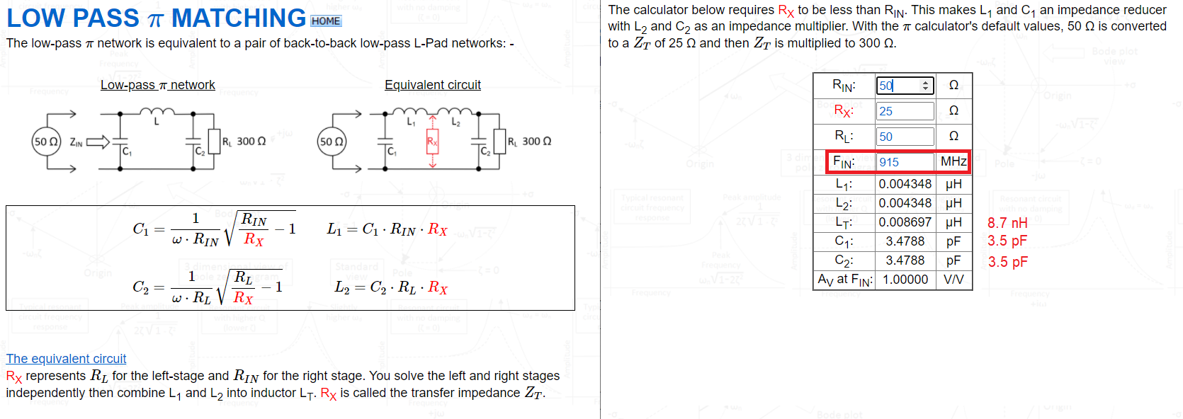
Picture and calculator can be found here.
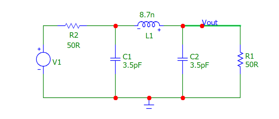
So, plugging the numbers into a simulator we get this circuit: -
And we get this AC response: -
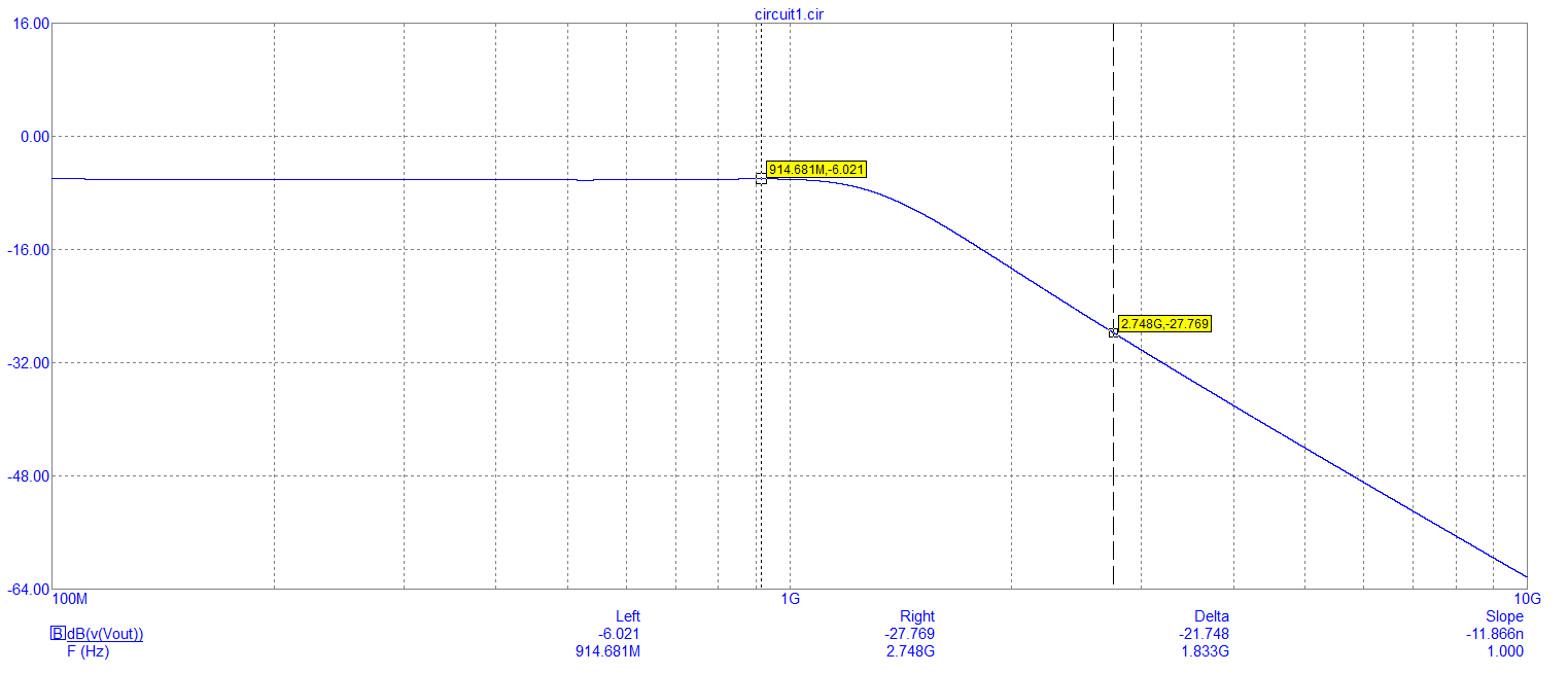
So, at 915 MHz we get the usual -6.021 dB input to output attenuation when you have matching input and output resistors (50 Ω) and, at the 3rd harmonic of 915 MHz we see an attenuation of 27.7 dB or, a relative attenuation of about 21.5 dB. Clearly that is very significant and, it's going to be even better at the sixth harmonic (around 40 dB I estimate).
But, remember, that at these frequencies, it's easy to get harmonic leakage to the output with badly chosen inductors and capacitors that are unsuitable for this application so, choose with care. Layout with care also.
If you need steeper roll-off above 915 MHz then the beauty about the
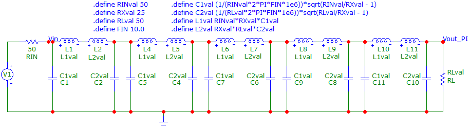
And here's the frequency response: -
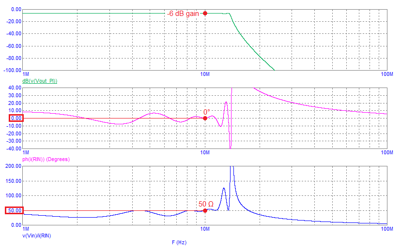
It's got perfect 50 Ω input and output impedance at 10 MHz and has rolled-off the 2nd harmonic (20 MHz) by around 70 dB.
We got a copy of the hardware and took a first crack using a lowpass Chebyshev filter at 950MHz (radio transmits up to ~930MHz).
On the first pass, we got a .2dBm drop on the fundamental [margin of error in our test chamber] and a 12db drop on the most severe harmonic.
I don't know if the Chebyshev cutoff at 930MHz vs. 950MHz, is going to have a huge impact on harmonics coming off the system 3GHz+. I'm not going to investigate further since we got such a great and easy result on the first pass.
Because we don't have any issues with other harmonics of the system, until like the 7th harmonic or so, a low pass filter totally worked here.
I didn't layout the board, but I'm super glad the layout guy decided to add in an additional PI network for future filtering.
I've impedance matched a few RF systems using a VNA, and if you have the space, those extra three components are life savers.
I've always gotten rock star results (way above FCC limits) after tuning up our systems.

1 comment thread