Comments on Meaning of some components around voltage reference in SMPS
Parent
Meaning of some components around voltage reference in SMPS
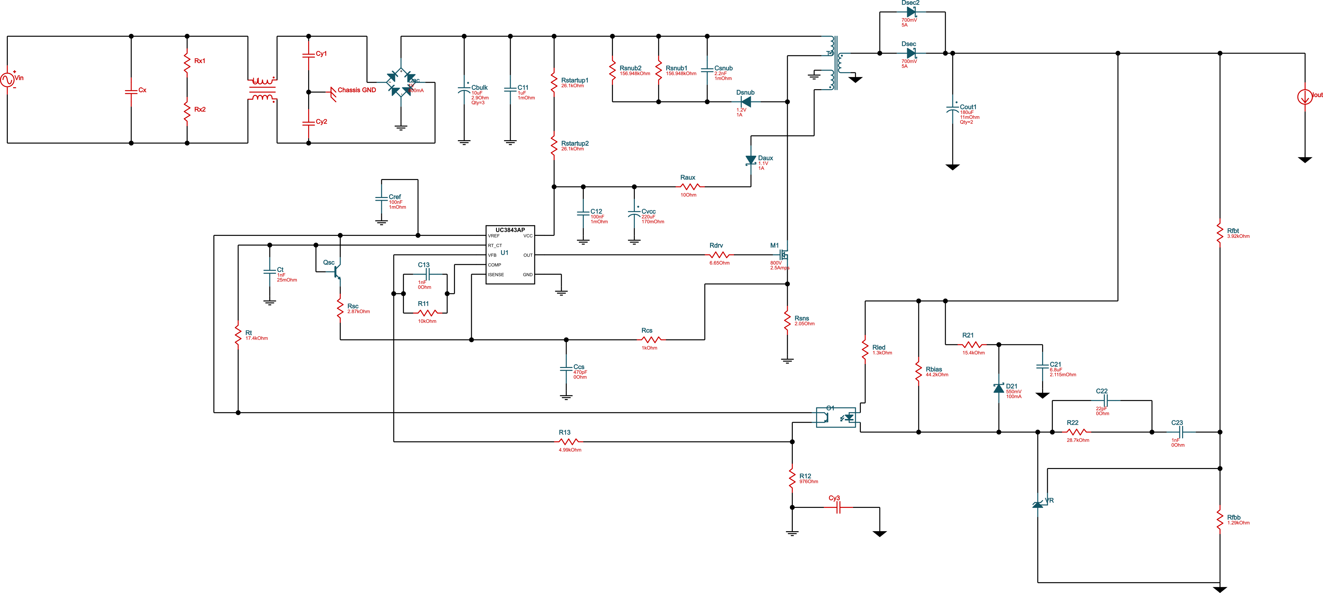
I have generated flyback convertor schematic by TI's Webench Power Designer.
Parameters:
- universal AC input (85-265V AC)
- 5V, 2A output
- isolated
- UC3843A controller
Basically I understand flyback topology, but I do not understand the function of some components around voltage reference (LMV431 used there).
What are R21, C21, D21 for? How to calculate values?
What are R22, C22, C23 for? How to calculate values?
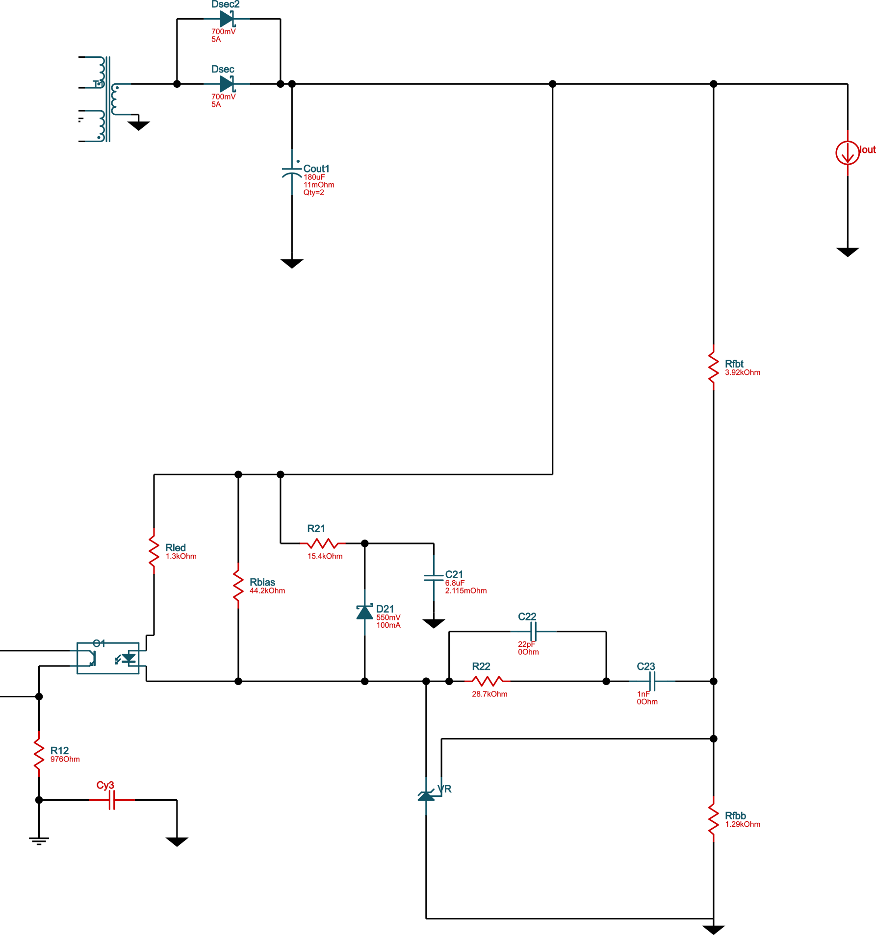
Just cut-out of the schematic:
Full schematic:
Post
At first glance, R22, C22, and C23 look like a compensation network around the TL431. However, this doesn't make much sense because the TL431 is being run open loop. Rfbt and Rfbb divide down the output voltage. The TL431 is turned on when that reaches 2.5 V. The TL431 is therefore used to compare the output voltage to its regulation threshold. When the voltage is above the threshold, the TL431 turns on, which turns on the LED in the opto, which then signals the controller to stop making pulses.
A more likely reason for the R22,C22,C23 network is a little feed-forward. This would change the signal thru the opto from a simple high/low indication to have a small transition region. In that region, the opto will dither, somewhat proportional to the output voltage within that narrow detection region. This was probably used for a little less ripple on the output than would have resulted from a pure high/low indication.
As for R21,D21,C21, I have no idea unless the signal at the top of D21 goes somewhere else that is not show. Without that, all that this circuit appears to do is dump a pulse of current on the TL431 whenever it switches on. I can't come up with a reason why you would want to do that. In fact, that seems like a bad idea, so I don't know what the point is.

0 comment threads