Communities

Writing
Writing
Codidact Meta
Codidact Meta
The Great Outdoors
The Great Outdoors
Photography & Video
Photography & Video
Scientific Speculation
Cooking
Cooking
Electrical Engineering
Judaism
Judaism
Languages & Linguistics
Software Development
Mathematics
Mathematics
Christianity
Christianity
Code Golf
Code Golf
Music
Music
Physics
Physics
Linux Systems
Linux Systems
Power Users
Power Users
Tabletop RPGs
Tabletop RPGs
Community Proposals
Community Proposals
tag:snake search within a tag
answers:0 unanswered questions
user:xxxx search by author id
score:0.5 posts with 0.5+ score
"snake oil" exact phrase
votes:4 posts with 4+ votes
created:<1w created < 1 week ago
post_type:xxxx type of post
Search help
Notifications
Mark all as read See all your notifications »
Q&A

Comments on Op Amp Hartley oscillator

Parent

Op Amp Hartley oscillator

+0
−2

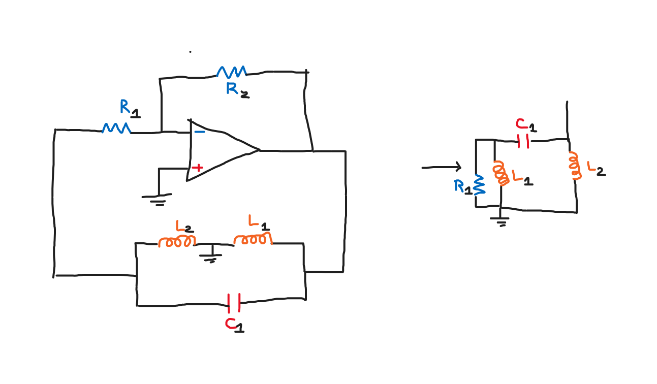
Im designing a Hartley oscillator this time with a opamp providing the open-loop gain.I have tried drawing the small-signal analysis of my circuit to use KVL and KCL to find the conditions of operation of my Hartley oscillator but now I am stuck.

How should I continue ?

History
Why does this post require moderator attention?
You might want to add some details to your flag.
Why should this post be closed?

2 comment threads

Incorrect schematic for a Hartley Oscillator (1 comment)
Use junction dots already! (2 comments)
Post
+1
−0

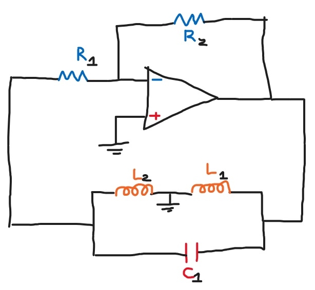
You are asking how to analyze this circuit:

Forget about what you think it should be called. Before attempting to model specific aspects, first try to understand the circuit.

The opamp provides gain of -R2/R1. For an ideal opamp, the output of the opamp has zero impedance in this circuit. That means anything between its output and ground, like L1, is irrelevant. That only influences how much current the opamp must source or sink to maintain the output voltage, but has no effect on that output voltage.

Step back and forget you ever heard of a "Hartley oscillator" (I'm not sure this qualifies as one anyway, but that's irrelevant). Instead of trying to figure out what some made-up circuit does, try synthesizing it instead. That will teach you a lot more about the final result.

So, you've got an amplifier with gain below -1. To make an oscillator, you need overall loop gain >1 at the desired oscillating frequency. Therefore, you need a feedback network that inverts at the oscillation frequency. Note that inversion is the same as 180° phase shift. Now actually stop and think how you'd achieve that with passive parts.

You should know by now that a LC high pass filter introduces some phase shift. A simple LC filter might not get the phase shift you need at the gain you need. However, two might more easily. There are various ways to achieve this. You might want to exploit resonance. I'm not going to do this for you because you clearly need to spend some time thinking about what the circuit is really doing qualitatively, instead of jumping straight to some formula that you found in a book somewhere.

We've reduced the problem to making a passive circuit that phase shifts at least some frequency by 180°, while not attenuating the result by more than a particular value. In this case, you have some latitude over the attenuation since you can compensate by increasing the gain of the opamp circuit. But, you can't go too far with that else the inverting opamp amplifier you have won't work as a simple R2/R1 gain anymore. Start with R2/R1 = 20. You really should be able to make a passive phase shifter that attenuates by less than 20.

History
Why does this post require moderator attention?
You might want to add some details to your flag.

2 comment threads

Not true -> Ideally, the output of the opamp has zero impedance. (2 comments)
Lowpass filter? (2 comments)
Lowpass filter?
LvW‭ wrote over 1 year ago · edited over 1 year ago

Just to avoid misunderstandings - the feedback network does not contain any lowpass filters.

The oscillators working principle is as follows:

The feedback network of a Hartley oscillator consists of a 3rd-order HIGHPASS filter in classical lader topology: Ro-L1-C1-L2. This highpass introduces 180 deg phase shift at one single frequency (oscillation frequency) which - together with an inverting amplifier - can fulfill the phase condition for oscillation.

However - as noted in the answer - the resistor Ro is missing in the shown circuit. This has happened because the whole topology was transferred from a transistor stage (with a finite output resistance) to an opamp-based amplifier without considering that the opamp output resistance is nearly zero.

Olin Lathrop‭ wrote over 1 year ago

Oops. I meant to say high pass. Fixed. It should be doable without the resistor on the output of the oscillator. The right LC network can use the fixed input impedance of the inverting amplifier to control Q.

I'm not sure the OP is ready for these details yet. I haven't seen any evidence that he's thought about what the feedback network really does, and how to go about designing one that achieves the goal.