Communities

Writing
Writing
Codidact Meta
Codidact Meta
The Great Outdoors
The Great Outdoors
Photography & Video
Photography & Video
Scientific Speculation
Cooking
Cooking
Electrical Engineering
Judaism
Judaism
Languages & Linguistics
Software Development
Mathematics
Mathematics
Christianity
Christianity
Code Golf
Code Golf
Music
Music
Physics
Physics
Linux Systems
Linux Systems
Power Users
Power Users
Tabletop RPGs
Tabletop RPGs
Community Proposals
Community Proposals
tag:snake search within a tag
answers:0 unanswered questions
user:xxxx search by author id
score:0.5 posts with 0.5+ score
"snake oil" exact phrase
votes:4 posts with 4+ votes
created:<1w created < 1 week ago
post_type:xxxx type of post
Search help
Notifications
Mark all as read See all your notifications »
Q&A

Comments on Battery protection circuit

Parent

Battery protection circuit

+4
−0

I am using two 18650 cells in series to power a RC car. Is the voltage goes below 6.2 V, the battery should be disconnected to prevent over discharging the battery. At the same time I want to implement reverse battery protection into the circuit. Since n-channel MOSFETs will be used for the H-bridge, therefore I want to use one for the reverse battery protection as well:

Reverse polarity protection

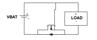
What kind of IC can be used to drive the MOSFET, so that when the voltage drops below 6 V the battery disconnects from the load? Is it possible to use a low voltage detector, for example R311x or TPS3840 or other, with a simple voltage divider? Or is there a better solution to this problem?

EDIT:

Would this circuit work? EDIT 2.0: The load and battery cells are supposed to be switched in this schematics. Schematics The trigger threshold is 4 V, so that when the battery voltage goes to 6 V the voltage supervisor will set the reset voltage to 0 V turning the upper MOSFET off.

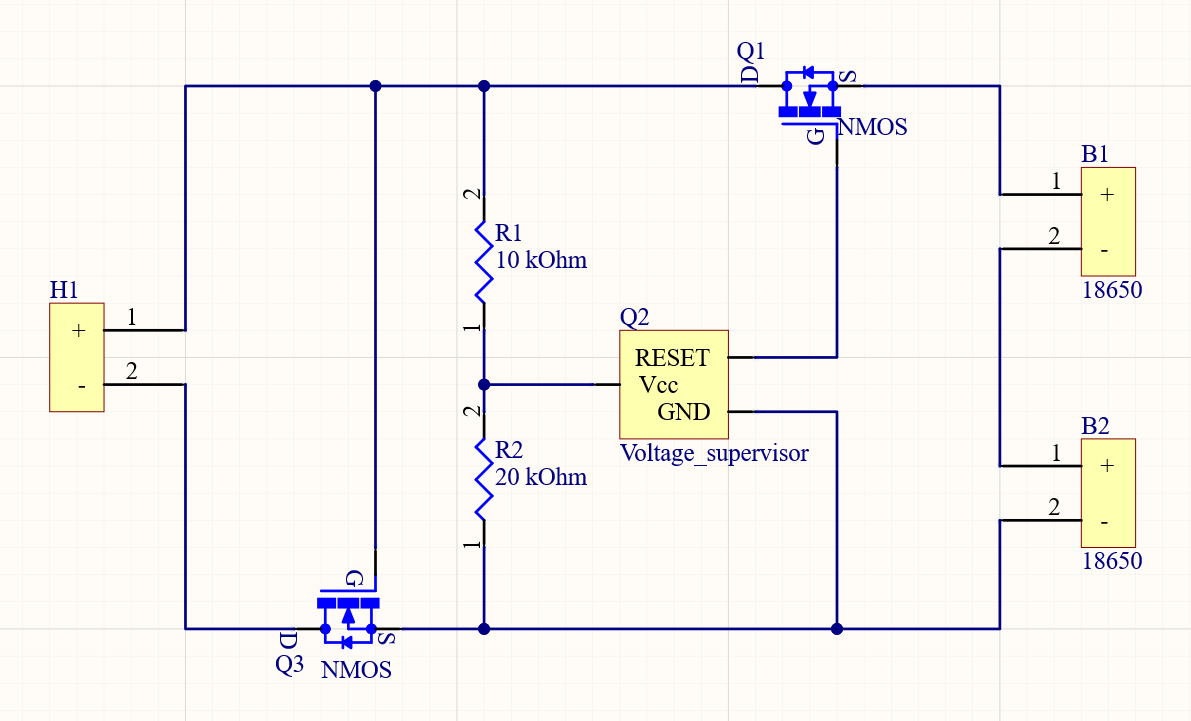
Another question, what will be the difference if instead of 10 kOhm and 20 kOhm, 10-times bigger values would be used?

History
Why does this post require moderator attention?
You might want to add some details to your flag.
Why should this post be closed?

0 comment threads

Post
+0
−1

This is the circuit I have decided to use: Schematics

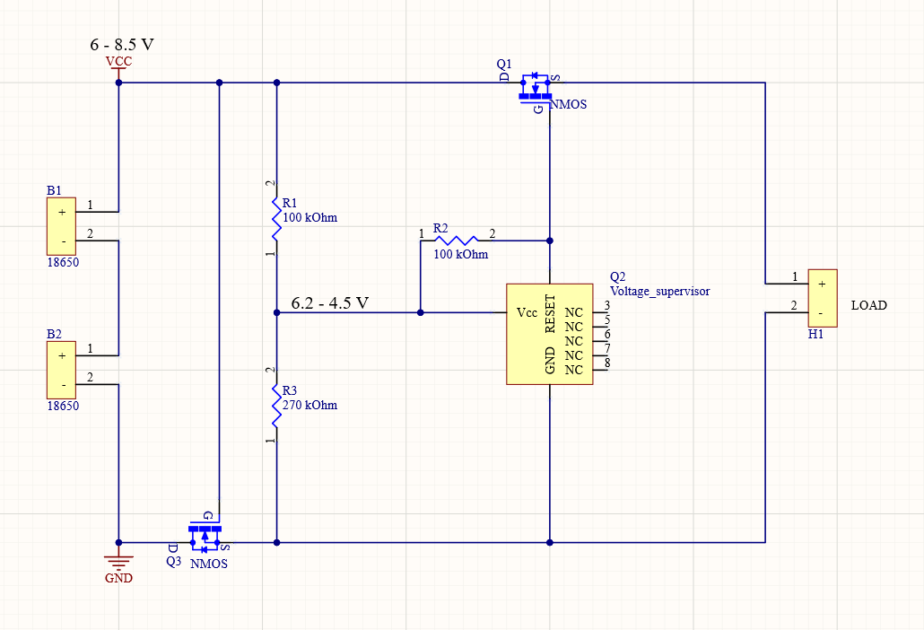
The cut-off voltage will be just above 6 V. MOSFETs used are SiRA14BDP and the voltage supervisor is TS831. Maximum current consumption of TS831 is just 12 uA.

For the voltage on one cell to hit dangerous level it needs to drop from 3 V to 2.5 V. From discharge rate characteristics of any 18650 cell we can get its capacity in voltage range 3 - 2.5 V. It will be anywhere from 0.1 Ah to 0.5 Ah. If we assume the worst case, the approximation for how long it will take for the cell to hit dangerous level is:

$$Time = \frac{Capacity}{I} = \frac{0.1 ~ Ah}{1\cdot 10^{-6} ~ A+12\cdot 10^{-6}~ A+\frac{6 ~ V}{270000~ \Omega}} ~ \approx ~ 2839~ hours$$

Where: $$I ~= I_{DDS} + I_{CC} + I_{voltage~divider}$$ Idds is zero gate voltage drain current. Icc is current consumption of the voltage supervisor.

Using this approximation we get that it would take over 100 days for the cells to hit 2.5 V. Using better 18650 cells that have 0.5 Ah capacity left at 3 V the time would be extended to almost 600 days.

History
Why does this post require moderator attention?
You might want to add some details to your flag.

1 comment thread

It will burn (6 comments)
It will burn
Andy aka‭ wrote over 1 year ago · edited over 1 year ago

The absolute maximum voltage the supervisor chip can survive is 7 volts. Two series batteries can be 8.5 volts when close to fully charged. And, if that wasn't a problem enough, you would need to use a PMOS FET in the positive lead else you could carry on discharging the battery through the MOSFET bulk diode.

Stefan‭ wrote over 1 year ago

The voltage divider makes sure that the voltage will remain at 6.2 V on the Vcc pin of the supervisor when the batteries are fully charged. As for the discharging of the battery trough the diode, do you mean the lower Q3 MOSFET? It will be switched on even after the voltage drops under 6 V. Yes there will be some power loss there...

Stefan‭ wrote over 1 year ago

Hi, i just noticed that the battery cells and load were switched on the schematics... I edited the post.

Andy aka‭ wrote over 1 year ago

I won't work using this type of chip with a massive impedance feeding the chip's Vcc pin. I've said enough on this subject now. Take heed or be prepared for disappointment.

Stefan‭ wrote over 1 year ago · edited over 1 year ago

I will try my luck one last time, and ask: In your answer you suggested using "low-power comparator to deactivate the added MOSFET". Did you mean something like TLV6713 or LM311?

Andy aka‭ wrote over 1 year ago

I hadn't really thought about an actual device but the TLV looks a decent choice.