H-Bridge components and calculations
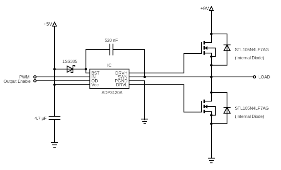
My goal is to make an RC car, and I have a couple of questions regarding driving the brushed DC motor. Schematic for half of my H-bridge looks like this for now (it will be identical on the other side):
I am trying to make a H-Bridge circuit to drive a brushed DC motor (Motor_Datasheet). It will be powered by two 18650 cells in series. I have decided to use 4 N-channel MOSFETs (Mosfet_datasheet). There are a couple of things I am not sure about.
Firstly, is this calculation for power dissipation correct? The first part is the conductive loss, that part I'm pretty sure is right. The second part concerning the switching losses is something I still do not fully understand, so some links to articles or short explanation of why it is in/correct would be appreciated.
P = (I^2 * R) + (I * V * (t_on+t_off)/2 * f) = 0.517 W
Where: I is the expected average current (10A), R is the drain-source on resistance (4.5 mOhm), V is the voltage of fully charged batteries (9V), t_on is calculated from the datasheet as t_don + t_r = 16.5 nS, t_off is calculated from the datasheet as t_doff + t_f = 58 nS, and f is the PWM frequency (20 kHz).
Another question is: Can this H-bridge be driven by two ADP3120A (ADP3110A) dual bootstrapped MOSFET drivers (Driver Datasheet). The MOSFET's input capacitance is typically 1500 pF, and the driver should be able to drive 3000 pF load. The difference between the ADP3120A and ADP3110A is that the first one has 45 nS propagation delay and a 25 nS transition time. The propagation delay of second one is 25 nS and transition time is 30 nS. How can these values be used to choose the right one?
Last thing: The Vcc to the ADP3120A should be >=5V. I want to use the 5V that will be used to power the MCU. But using higher voltages is preferred, according to the datasheet. Would it be possible to drive it from the same source as the motor? Or would powering it from two 18650 cells in series be a problem since the voltage will go from 9V (probably less) to approximately to 6.4V. Is the change in Vcc of the driver during operation something to avoid?
1 answer
Firstly, is this calculation for power dissipation correct?P = (I2 * R) + (I * V * (t_on+t_off)/2 * f) = 0.517 W
Not completely. There are two separate parts that need to be considered. I2RDSON is the power dissipated by the FET when on. However, you can't use the average current. You have to average the power dissipation instead. AVE(I2)R is not the same as AVE(I)2R.
The other part accounts for the FET dissipating when it's partially on. If the load is purely resistive, then the worst case dissipation happens when the FET is dropping half the available voltage. The output current would then also be half, so the dissipation would be ¼ of the full current times the full voltage. Dissipation will vary over a switching transition, but using IV/4 is probably reasonable, then being conservative and assume this applies during the full switching time.
In practice, the FET will transition thru the high-dissipation region quite quickly. The FET datasheet will give a lower limit on this time if the gate voltage were changed instantly, but that's not going to happen. In the end, it's really hard to guess at the switching losses because of too many unknowns. You could look at the FET driver output current capability against the worst case total apparent gate capacitance, and come up with a transition time. That twice per cycle times IV/4 might at least give you a rough idea where you're at.
At 20 kHz switching, meaning one transition per 25 µs on average, the on-time dissipation will likely dominate.
The difference between the ADP3120A and ADP3110A is that the first one has 45 nS propagation delay and a 25 nS transition time.
This is irrelevant. Delay doesn't matter in your application. What you care about is fast switching, regardless of how late that happens after an input transition. The only issue with delay is if it's asymmetric between the rising and falling edge. That will change your PWM duty cycle slightly. The outer control loop should compensate, and the rest of the system never knows it happened.
The other problem with asymmetric delay is if it causes shoot-thru. However, your driver chip claims to be specifically designed to avoid that, so nothing to worry about there.
The Vcc to the ADP3120A should be >=5V. I want to use the 5V that will be used to power the MCU. But using higher voltages is preferred, according to the datasheet. Would it be possible to drive it from the same source as the motor?
The answer to this is in the datasheet. The top line on page 4 says the operating voltage is from 4.6 to 13.2 V. Two lithium cells in series might be as high as 8.5 V, certainly well below 13.2 V. Therefore, the FET driver can be run directly from the motor supply.
The remaining question is then what level the digital input signals need to be. Note that minimum guaranteed high for both inputs is 2.0 V. It seems the FET driver was deliberately designed to work with 3.3 V logic signals in, while powered by a higher voltage.
Other issues
You really need to nail down your maximum current. The motor datasheet says that the expected current is 19 A at one operating point with 7.2 V applied. Note that the stall current is 109 A, although the voltage is not specified. That's a crappy datasheet, which is unfortunately typical of far east motor manufacturers.
It's quite a beast of a motor, and not really a good match with two 18650 cells. You should start by finding how much power this "RC car" really needs. If it's one of those toys meant to run around on the living room rug, then this motor is gross overkill, and will cause trouble.
If this car is actually much bigger and it really takes 100 W to move it along worst case, then you need to re-think your power source. Make sure the battery pack can deliver both the current and power. Can each cell really source 50 W and 23 A? Probably not.
0 comment threads

0 comment threads