Communities

Writing
Writing
Codidact Meta
Codidact Meta
The Great Outdoors
The Great Outdoors
Photography & Video
Photography & Video
Scientific Speculation
Cooking
Cooking
Electrical Engineering
Judaism
Judaism
Languages & Linguistics
Software Development
Mathematics
Mathematics
Christianity
Christianity
Code Golf
Code Golf
Music
Music
Physics
Physics
Linux Systems
Linux Systems
Power Users
Power Users
Tabletop RPGs
Tabletop RPGs
Community Proposals
Community Proposals
tag:snake search within a tag
answers:0 unanswered questions
user:xxxx search by author id
score:0.5 posts with 0.5+ score
"snake oil" exact phrase
votes:4 posts with 4+ votes
created:<1w created < 1 week ago
post_type:xxxx type of post
Search help
Notifications
Mark all as read See all your notifications »
Q&A

Comments on Buck-boost converter fed from split input supply

Post

Buck-boost converter fed from split input supply

+5
−0

I have recently finished designing a buck-boost converter for a job that uses a split (+/-) input power supply. Load power is taken equally from both positive and negative input supplies and, the load is connected to 0 volts (mid-rail of the split input supply).

$$$$

For a single rail supply, the standard approach would be this: -

Image alt text

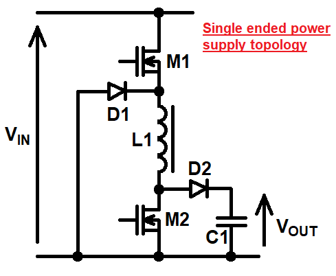
I've not shown the MOSFET drive circuits because they're unimportant. So, my question is this: what design approach/topology would you choose when designing a buck-boost controller that operates from a split input power supply and drives a load connected to 0 volts.

$$$$

I'm looking for a basic circuit idea like the one above i.e. no need to show drivers etc..


Edited section

Olin came up with a solution using a transformer and thumbs-up for that but, I'm actually interested in a solution that doesn't use a transformer. I'm also interested in power levels of above 1 kW.

  • The input supply is +/-250 volts DC.
  • DC output is variable between 300 volts and 600 volts.

My recently finished solution seemed novel because I couldn't find it when searching the internet. Hence, I'm interested if anyone else has a standard solution that matches what I came up with.

Sorry for not making these things clear at the outset.

History
Why does this post require moderator attention?
You might want to add some details to your flag.
Why should this post be closed?

3 comment threads

It seems you still use the single-ended topology but integrate current offset error with Hall, Rs or ... (2 comments)
Andy, the input to the buck-boost is between the Vin+ and Vin-. I'm guessing that the load will be b... (3 comments)
Does that mean you want it direct coupled but behave like a transformer AC coupled? Then the PFM or... (2 comments)
Does that mean you want it direct coupled but behave like a transformer AC coupled? Then the PFM or...
TonyStewart‭ wrote over 1 year ago · edited over 1 year ago

Does that mean you want it direct coupled but behave like a transformer AC coupled? Then the PFM or PWM drivers must have error feedback for the integral sum of current sensed from each to null the DC current and voltage feedback to null the error from the input voltage. So the answer lies in the sensed current and the driver signals you want to ignore. I guess this is a Class E or similar with some unspecified load.

Andy aka‭ wrote over 1 year ago · edited over 1 year ago

No, I just don't want to use a transformer. Sure there's current sensing and voltage sensing and specialty drivers but these are beyond what I'm asking about. Basically, how would you configure the single ended power supply version to work with split input supplies is what I'm asking.