Communities

Writing
Writing
Codidact Meta
Codidact Meta
The Great Outdoors
The Great Outdoors
Photography & Video
Photography & Video
Scientific Speculation
Cooking
Cooking
Electrical Engineering
Judaism
Judaism
Languages & Linguistics
Software Development
Mathematics
Mathematics
Christianity
Christianity
Code Golf
Code Golf
Music
Music
Physics
Physics
Linux Systems
Linux Systems
Power Users
Power Users
Tabletop RPGs
Tabletop RPGs
Community Proposals
Community Proposals
tag:snake search within a tag
answers:0 unanswered questions
user:xxxx search by author id
score:0.5 posts with 0.5+ score
"snake oil" exact phrase
votes:4 posts with 4+ votes
created:<1w created < 1 week ago
post_type:xxxx type of post
Search help
Notifications
Mark all as read See all your notifications »
Q&A

Comments on Ceramic filter vs ceramic resonator

Post

Ceramic filter vs ceramic resonator

+2
−0

I have a design of a power line communication using the following IC.
https://www.yamar.com/datasheet/DS-SIG60.pdf

My design is the same as the example circuit in the datasheet of the chip.

Schematic

The schematic above uses integrated ceramic filters. There are also some suggested part numbers in the datasheet.
However I can't find any in the market.
This is the part I'm looking for: LTSH6.0MDB

But I can find many ceramic resonators and crystal resonators instead.

What is the difference between a ceramic filter and a ceramic resonator?

I have placed a ceramic resonator instead.
This is the part number I placed instead in the position of F0.

CSTCR6M00G53-R0

Of course I have set up the chip to work at 6MHz (Instead of 5.5MHz which is the default) frequency because that component has center frequency 6MHz.
But still it doesn't seem to work as expected.
I can receive bytes but there's a lot of garbage in the communication.

F1 is optional and I didn't include it in the design.

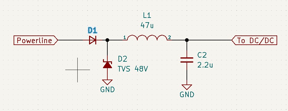
I use it for powerline communication over DC voltage 12V to 36V.
I have also included the proper low-pass DC filtering in its DC/DC power supply in the board. As mentioned in the datasheet. LPF

I think the problem is in the ceramic resonator I put instead of a ceramic filter (that's why the title). However despite that I can see signal comming on the analog parts of the chip, with my oscilloscope. The amplitude of that signal is above 1Vpp, around 2Vpp. Which is way enough for a proper communication according to specs.

History
Why does this post require moderator attention?
You might want to add some details to your flag.
Why should this post be closed?

1 comment thread

Data sheet links needed (5 comments)
Data sheet links needed
Andy aka‭ wrote over 1 year ago

Data sheet links needed for the ceramic parts. Circuit diagram of the low pass-filters on the DC bus needed. Have you tried connecting two units directly to see that they work on an exclusive connection?

DeadMouse‭ wrote over 1 year ago · edited over 1 year ago

Datasheets and screenshot added. What do you mean by exclusive connection? The tests are on a bench and the devices are communicating over a DC line of 24V.

Andy aka‭ wrote over 1 year ago

Try a direct communication to rule out DC filters affecting the comms.

DeadMouse‭ wrote over 1 year ago · edited over 1 year ago

You probably mean connecting the outputs (right part of C4) together and off of DC line, right?
Thank you! I'll try it.
Regarding the main question, what's the difference between those two components above (a ceramic filter and a ceramic resonator)?

Is the part I found suitable for that application?

Andy aka‭ wrote over 1 year ago

Try directly connecting the lines without any hinderance and see what the result is. Proceed with that situation until its fixed then, move onto coupling via the power rails.

Skipping 1 deleted comment.