Communities

Writing
Writing
Codidact Meta
Codidact Meta
The Great Outdoors
The Great Outdoors
Photography & Video
Photography & Video
Scientific Speculation
Cooking
Cooking
Electrical Engineering
Judaism
Judaism
Languages & Linguistics
Software Development
Mathematics
Mathematics
Christianity
Christianity
Code Golf
Code Golf
Music
Music
Physics
Physics
Linux Systems
Linux Systems
Power Users
Power Users
Tabletop RPGs
Tabletop RPGs
Community Proposals
Community Proposals
tag:snake search within a tag
answers:0 unanswered questions
user:xxxx search by author id
score:0.5 posts with 0.5+ score
"snake oil" exact phrase
votes:4 posts with 4+ votes
created:<1w created < 1 week ago
post_type:xxxx type of post
Search help
Notifications
Mark all as read See all your notifications »
Q&A

Comments on What are these transformer graphs about?

Post

What are these transformer graphs about?

+1
−1

This picture describes the behaviour of a single phase transform under resistive,inductive and capacitive loads(from left to right)

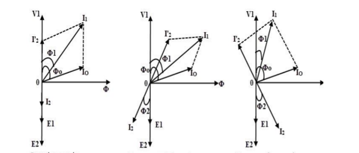
How what exactly is $V_{1}$ ?Is it the voltage at the primary side?And what are $I^{'}_{2}$ , $I_{1}$ and $I_{0}$? Is $I^{'}_{2}$ the current at the secondary side?If $I^{'}_{2}$ is the current at the secondary side then there is no way $V_{1}$ is the voltage at the primary side because in the first out of the 3 pictures(from left to right) there is a 0 degrees phase difference between $V_{1}$ and $I^{'}_{2}$ and by taking the transformer's equivalent circuit:

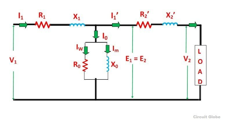
and ignoring the branch related to the core of transformer,the transformer itself has a inductive behaviour due to the inductance of the primary and secondary windings so $V_{1}$ cannot be the primary voltage simultaneously with $I^{'}_{2}$ being the secondary current.

So what are the quantities of these graphs?

History
Why does this post require moderator attention?
You might want to add some details to your flag.
Why should this post be closed?

2 comment threads

Pictures not matching (2 comments)
Show context (3 comments)
Pictures not matching
Andy aka‭ wrote 11 months ago · edited 11 months ago

Your upper picture of the phasors shows $I_2$ and $I'_2$ <-- they don't appear in the equivalent circuit shown below. Consistency is needed to give an answer. Neither do the loads (if I read the phasor diagrams correctly), match truly capacitive or truly inductive loads. The resistive load scenario appears to match. The capacitive-orientated diagram also seems to be for the inductive-orientated diagram

You need to provide clarity. A bit of a mess really.

Volpina‭ wrote 11 months ago

The image of the equivalent circuit of a transformer and the diagrams of the operation of a transformer under different loads dont come from the same source so the labels dont match. A inductive or a capacitive load isnt a pure inductor or a pure capacitor its a combination of a series resistance with a inductor or a capacitor.