Comments on Over-voltage protection for device with photovoltaic cell source
Parent
Over-voltage protection for device with photovoltaic cell source
I have a solar panel rated for 6V open-circuit and up to 150mA. I would like to connect this to an SPV1040 or similar buck-boost converter with MPPT functionality to be able to charge a 3.6V battery under cloudy conditions.
The problem is that the SPV1040 has a maximum input voltage of 5.5V, while the panel is rated for 6V and I have measured up to 7.5V in sunny conditions. Of course, 6V is an open-circuit specification and the 7.5V measurement was open-circuit as well. I read that the maximum power point is usually around 75% of the open-circuit rating, which would give 4.5V which is below the 5.5V maximum rating of the SPV1040.
Would it still be necessary or sensible to place a zener diode voltage regulator in front of the SPV1040 to make sure the input voltage will not exceed 5.5V? If so, is it necessary to have a resistor in series with the zener diode to limit the current? I can imagine that since the power source is current limited anyway this may not be needed, and I don't want to waste power in the resistor in the common case that the zener diode is not dissipating any power. So, given the 6V open-circuit and a 5.5V zener diode that can handle 150mA, do I need the resistor in this circuit?

Or am I going about this wrong and is another type of over-voltage protection preferable?
(I have also looked for other buck-boost converters with MPPT functionality and a wider input voltage range, but without success. There is the LTC3119, but it is far more complex (and expensive). Other chips with a higher maximum input voltage typically also have a higher minimum input voltage, which is not ideal; or they are only available in packages that I wouldn't be able to solder by hand.)
Post
This IC is not well suited for the task.
MPPT (Maximum Power Point Tracking) relies on matching impedance according to the maximum power transfer theorem. However, in the case of a photovoltaic array (PV), it functions as a current source with a voltage limit (Voc) and a short circuit limit (Isc). The load line representing Voc/Isc=Rmpp, which is the effective incremental resistance at the maximum power point (MPP), is transferred due to the MPT theorem. However, unlike in 50 ohm systems with 50% loss, this is a current source, resulting in a different scenario.
The incremental resistance is not Vmpp/Impp, but rather the derivative or slope of the V vs I curve at MPP.
This information is not commonly taught, but is based on personal experience. It is worth noting for professors.
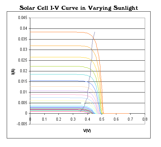
If you refer to the quadratic points on the MPT curve on Wikipedia, you will find that at full sun, Vmpp/Voc is approximately 82%, and this drops to 72% at half sun. Therefore, if Voc=7.2V, 82% of this is 5.9V, which is close to the MPP voltage for full sun. Ideally, to transfer this current to a battery, a 5 to 6V battery without an MPP is desired.
There are better plots but this shows the Voc, Ioc and MPP quadratic set of points. Take your Voc values and scale them to choose the % of Voc for the MPT point or MPP.
You can use a suitable 6V battery to store enough energy for a few days then a MOSFET LDO with a much less than 0.5V min. dropout.
What this means is you average solar current, voltage or power must exceed the average load of your application to sustain 5V. There is no lossy tracking of MPPT but rather using the best 5 to 6.5V battery to store linear charging and then never draw more average energy than being supplied. The LDO ought to have a heatsink if you need a power burst that raises it's temperature and use your Thermodynamic thermal resistance rules.
For a 150 mA PV array, I think this is a sensible open loop design.
1 comment thread

0 comment threads