Communities

Writing
Writing
Codidact Meta
Codidact Meta
The Great Outdoors
The Great Outdoors
Photography & Video
Photography & Video
Scientific Speculation
Cooking
Cooking
Electrical Engineering
Judaism
Judaism
Languages & Linguistics
Software Development
Mathematics
Mathematics
Christianity
Christianity
Code Golf
Code Golf
Music
Music
Physics
Physics
Linux Systems
Linux Systems
Power Users
Power Users
Tabletop RPGs
Tabletop RPGs
Community Proposals
Community Proposals
tag:snake search within a tag
answers:0 unanswered questions
user:xxxx search by author id
score:0.5 posts with 0.5+ score
"snake oil" exact phrase
votes:4 posts with 4+ votes
created:<1w created < 1 week ago
post_type:xxxx type of post
Search help
Notifications
Mark all as read See all your notifications »
Q&A

Comments on Confusion in operation of analog computer

Post

Confusion in operation of analog computer

+1
−1

I am studying for a test in control systems and we have a practical part which is to program a analog computer.

Here is a picture of the analog computer:

Image alt text

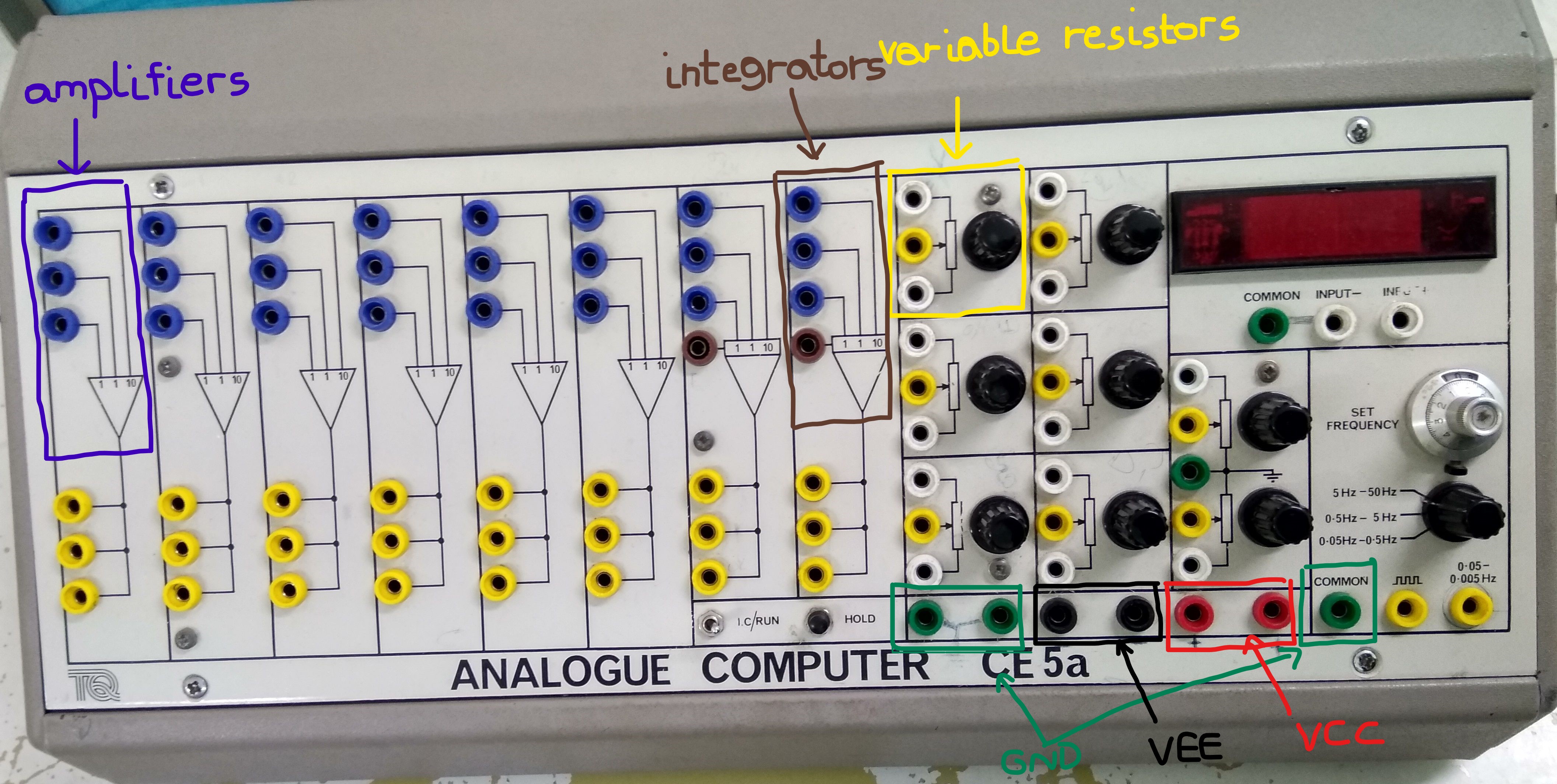
The variable resistor is basically a voltage divider between VCC and VEE and you can change the output voltage by changing the position of the potentiometer.

Suppose we have this block diagram

Image alt text

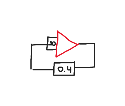
We set the potentiometer to multiply the signal it sees by 0.4 then return to the input of a amplifier.Next to the potentiometer there are 3 pins the top pin and bottom pin are connected internally to VCC and VEE and the middle pin is the voltage division.When we are done setting the value of the potentiometer and connect the middle pin to the input of a amplifier and we are ready to measure the output voltage with a oscilloscope do we still keep the top and bottom pins plugged to power or not?Will I create a short if I keep the top and bottom pins plugged to power?

History
Why does this post require moderator attention?
You might want to add some details to your flag.
Why should this post be closed?

2 comment threads

What rotary switch? (5 comments)
Block diagram is meaningless (2 comments)
What rotary switch?
Olin Lathrop‭ wrote 11 months ago

I looked at your full image carefully, and the only rotary switch selects one of three frequency ranges for the built-in square wave generator. The silver-colored 10-turn knob above the rotary switch provides the fine adjustment. I see no rotary switch where "set the rotary switch to multiply the signal it sees by 0.4" makes any sense.

Volpina‭ wrote 11 months ago

Well how do you call the switch which sets the output voltage of the variable resistor?Isnt that a rotary switch?

Olin Lathrop‭ wrote 11 months ago · edited 11 months ago

No, those are pots (potentiometers). You even label them yourself as variable resistors. Remember, this is an analog computer. Switches are digital.

Volpina‭ wrote 11 months ago · edited 11 months ago

Ah i thought because you rotated it to change values is a rotary switch ,I have never seen a potentiometer in the form as shown in the picture.

Olin Lathrop‭ wrote 11 months ago

I don't know what other form you've seen pots in, but a rotating shaft is very common. In any case, you need to fix the question.