Constant Current Load Circuit with Op Amp
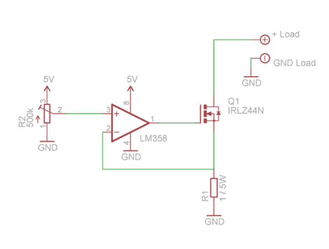
Hi, I built a constant current load following the circuit from https://www.instructables.com/id/DIY-Constant-current-load/
But my op amp gets destroyed after a few minutes. The transistor or the op amp didnt get hot to the touch. After replacing the op amp the circuit works again for a short time.
Am I at fault or is the circuit wrong? Tested at 10V 0.5A.
P.S. It is working again as of now. But still I have destroyed a couple op amp. Is there a better circuit design? Like mentioned here https://electronics.stackexchange.com/questions/371864/constant-current-load-op-amp-ref-voltage-limit
2 answers
You are accessing this answer with a direct link, so it's being shown above all other answers regardless of its score. You can return to the normal view.
Assuming nothing is broken or wired incorrectly, this is most likely the result of the opamp oscillating wildly. The average may still be about what it should be, so you might not notice with only a meter. Put a scope on G and S of Q1.
Oscillation should be no surprise, since it's quite possible that the opamp is running with a gain below 1 over some part of the range. The LM358 is only claimed to be stable down to a gain of 1. Small voltage changes on the gate of the FET could actually cause larger voltage changes on the source. This is just asking for instability.
In general, it's good to lay out a circuit like this with a place for a compensation cap. Put a resistor in series with the negative input, then at least leave pads for a cap between the opamp output and its negative input.
Start with 1 kΩ between R1 and the negative opamp input, then 10 nF between the opamp output and negative input. That's probably overkill, but if you don't need particularly high bandwidth, then maybe it's fine. If you need higher bandwidth, try successively lower capacitors until you can see some oscillation, then back up and at least double the cap.
When looking for oscillation, you have to slowly sweep over the whole current range. Or, slowly adjust R2, then watch for the setting where the gate voltage changes the least. This is where the opamp is being run at the lowest gain. Still, you have to check at least a bit on either side of the set point looking for oscillations to make sure there aren't any.
I need R1 to be low
If that were all there is to it, then you could replace R1 with a short.
It's a tradeoff, of course. Lower R1 uses up less voltage, increasing the compliance range. It also causes lower power dissipation. On the other hand, lower R1 lowers the accuracy, lowers the quality of the regulation, and makes the output more susceptible to other errors in the system.
If you're OK with the current sink requiring a bit more than 5 V worst case, then set R1 so that you get the largest current you will ever need when R2 is set to maximum.
the oscillation at the gate of the MOSFET makes the current constant
What!!? The opamp shouldn't oscillate at all. As I said above, this may well be why it is dying. I also described how to fix is so that it doesn't oscillate.
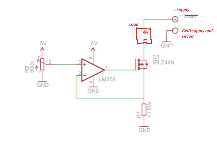
let me begin with a schematic for an adjustable current source with a simple load:
The operation is simple: The current I inside R1 gives rise a voltage drop equal to
I/R1 (= I if R1 = 1).
So the oamp will set the voltage to the gate of the mosfet in such a way that
I/R1 = V_pot, that is, I = R1 V_pot = V_pot if R1 = 1.
Since V_pot varies between 0 and 5V, I varies between 0 and 5 amp. So, the resistor should be rated for 25W (=1 ohm * (5A)^2 ) otherwise it will burn (assuming your supply and mosfet will not burn before it). I suggest to put a 500k resistor between the pot and the 5V supply, in order to make V_pot vary between 0 and 2.5V. In this way, the maximal power dissipated by the resistor will be about 5W.
Now, regarding the schematic you posted, it is not a constant current source for an usual load, but a constant current source for testing a battery, that is, the battery under test IS the power supply (and there is no load). Apart from that, everything is the same. That means that it should work up to 5V if the battery is able to feed 5A. In this way, you can measure the maximal current the battery is able to deliver (or more precisely, if it fits its compliance), by simply measuring the voltage at R1 (recall that the voltage is equal to the current because R1 = 1Ohm). Normally, there is no reason the circuit do not work, except that you may have wired the oamp wrongly, or a perverse connection etc. Nevertheless, to religiously protect the oamp, I suggest to put a 1k resistor between the out of the oamp and the gate of the mosfet. This will also prevent possible destructive oscillations and everything should work fine. So, the improvements I suggest are:
- 500k resistor between the pot and the 5V supply, or a resistor rated 25W.
- 1k resistor between the out of the oamp and the gate of the mosfet
- Oh, and of course a heat sink for the transistor, otherwise it may well burn.

1 comment thread