Post History
I've been experimenting with LC filter circuits on the output of a SMPS I recently bought because it was too high for the circuit I'm making. After hooking up many different combinations, I found t...
#2: Post edited
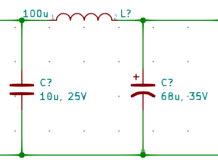
Hello,- I've been experimenting with LC filter circuits on the output of a SMPS I recently bought because it was too high for the circuit I'm making. After hooking up many different combinations, I found that this PI filter worked best for my load:
- 
- I'm trying to understand why this worked better than the two ceramic capacitor setup. My guess is the low ESR = more ringing? Is it standard to use electrolytics with this kind of filter? I guess I was really hesitant to use it because I couldn't find any examples online of electrolytics being used and the internet keeps shouting about how great MLCCs are.
P.S. Is it also better to use 3x22uF electrolytics instead or one bigger 68uF one?Thanks
- I've been experimenting with LC filter circuits on the output of a SMPS I recently bought because it was too high for the circuit I'm making. After hooking up many different combinations, I found that this PI filter worked best for my load:
- 
- I'm trying to understand why this worked better than the two ceramic capacitor setup. My guess is the low ESR = more ringing? Is it standard to use electrolytics with this kind of filter? I guess I was really hesitant to use it because I couldn't find any examples online of electrolytics being used and the internet keeps shouting about how great MLCCs are.
- P.S. Is it also better to use 3x22uF electrolytics instead or one bigger 68uF one?
#1: Initial revision
LC Filter and Capacitor Considerations
Hello, I've been experimenting with LC filter circuits on the output of a SMPS I recently bought because it was too high for the circuit I'm making. After hooking up many different combinations, I found that this PI filter worked best for my load:  I'm trying to understand why this worked better than the two ceramic capacitor setup. My guess is the low ESR = more ringing? Is it standard to use electrolytics with this kind of filter? I guess I was really hesitant to use it because I couldn't find any examples online of electrolytics being used and the internet keeps shouting about how great MLCCs are. P.S. Is it also better to use 3x22uF electrolytics instead or one bigger 68uF one? Thanks


