Battery backup voltage regulator (an invention story)
Goals and objectives
Motivation. Inspired that there is a place on the web where simple but clever circuit ideas are encouraged, I decided to share another 1-transistor circuit trick. Besides, to make the story even more interesting than before, I decided to show, step-by-step, how the circuit was (could be) "invented"... as an example of an inventing procedure. Thus, visitors to the new platform will not only get acquainted with a simple but clever device but will also get an idea of how they can invent such devices themselves... and that would be great. So I have two goals - one is specific (1-transistor device) and the other is general (technology of invention).
Background. My story is based on an inherent BJT property that sometimes causes strange problems - when is fully on, the base-emitter junction actually connects, like a forward biased diode, the base to the emitter; thus the input voltage source is directly connected to the emitter. For example, this situation can happen in an emitter follower, if the emitter ceases, for some reason, to follow the base. Usually, this is an undesired situation but here I will show one of its useful applications in power supplies equipped with a backup battery.
History. This idea came to me in the early 90's when I had to develop a simple power supply for home burglar alarm systems (at that time, the electricity was often interrupted here and alarm systems had to be backed up; now it is mandatory). Although this was a long time ago, the idea is still relevant and worth considering. Here is a possible scenario of the "inventing" procedure...
“Inventing” the circuit
1. Unregulated power supply. If we supply the load directly by an unregulated power supply (consisting of a transformer, diode rectifier and filter) - Fig. 1, the voltage will vary for various reasons - because the mains voltage varies... or because the load varies... or both. For simplicity, I have designated the mains supply voltage BIN with the battery symbol.
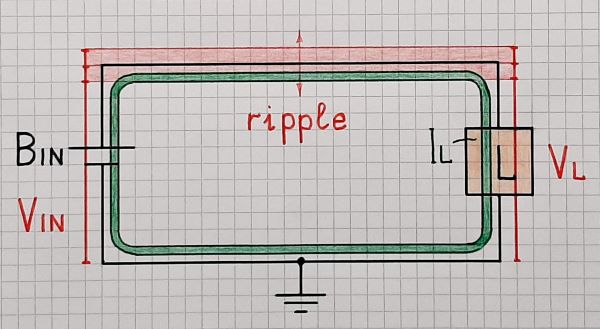
Fig. 1. Supplying a load by an unregulated power supply BIN (designated with a battery symbol).
2. Regulated power supply. So we have to somehow keep the voltage across the load constant. The best way to do it is like we do everything in life - to keep it equal to another but reference (desired) voltage VREF. For this purpose we compare them and change the voltage in the necessary direction until the difference between them becomes zero. This procedure is called (not very appropriate) "negative feedback".
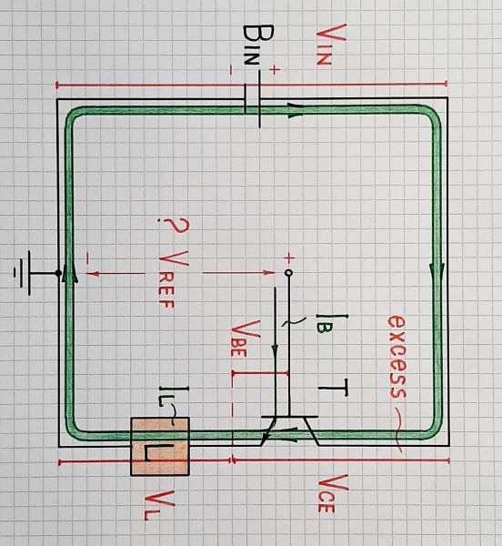
Fig. 2. Regulating the load voltage VL by means of the negative feedback (an emitter follower with a constant input voltage)
To implement it, we need a comparator and a regulating element. Both can be implemented by only one bipolar transistor - Fig. 2. The base-emitter junction is its (floating) input and the collector-emitter junction is the regulating element. The transistor "observes" the difference between the reference voltage VREF and the load voltage VL and changes its current until makes them (almost) equal. Figuratively speaking, the transistor acts as a "variable resistor" that changes its static resistance to change the current. This arrangement is known as "emitter follower".
The question now is, "Where do we get the reference voltage from?"
3. Battery backup voltage regulator. It is common to take it from the input unregulated voltage through a voltage divider of two resistors (bad) or a resistor and a zener diode (good). But here it turns out that we do not have a suitable Zener diode at hand... and then we come up with a simple "temporary" solution - to include a battery producing the voltage VREF - Fig. 3. Why not?
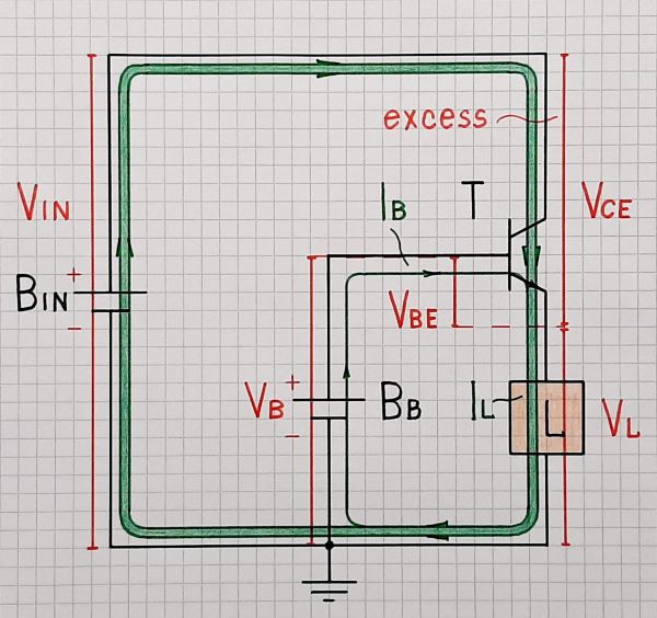
Fig. 3. Using a battery as a reference voltage source ("Zener diode").
The battery provides the small base current needed to set the beta times higher collector current and, accordingly, the load current needed. As though, Bb tries to supply the load by injecting the small base current through the base-emitter junction to the load and Bin (T) "helps" it by adding beta times bigger collector current.
4. Battery backup voltage regulator. Here, too, chance intervenes and helps us make the "invention". Accidentally, the input voltage interrupts... but to our surprise, the load (alarm system) continues to operate at normal voltage. Why? Where does this voltage come from?
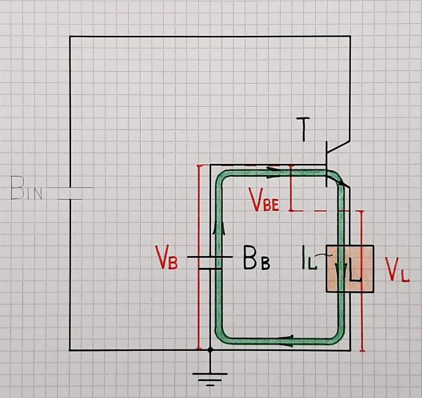
Fig. 4. An accidental invention of a battery backup supply - the battery supplies the load directly through the base-emitter junction.
Yeah, that is what it was - the battery voltage VB, which is transferred directly through the base-emitter junction as through a forward-biased diode. But wait... we can use this "failure" for something useful - to back up the supply voltage! This way we will not need additional diodes to switch the voltages.
This is a "2 in 1" solution since the single transistor does two things - regulates the input voltage and switches the voltages. Note that in the second mode (VIN failure) actually the transistor is not a transistor; it is used as a diode. The whole load current flows through the base-emitter junction acting as a diode. The battery Bb is also "2 in 1" since it serves both as a reference voltage source and backup battery.
5. Making the backup battery chargeable. The arrangement above works in this form as well. The base current is negligible and the battery will last maybe for a few months. But it is good to be rechargeable and to ensure its continuous charging. The simplest solution is through a resistor R - Fig. 5.
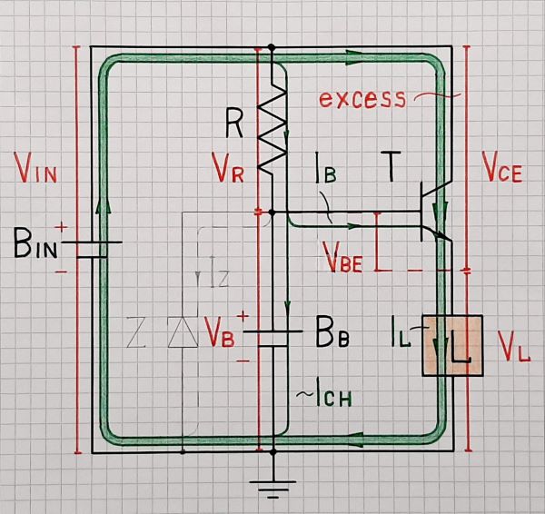
Fig. 5. Rechargeable battery backup voltage regulator
If you are afraid that the battery will overcharge, you can connect a Zener diode in parallel.
6. Charged battery supplies the load.
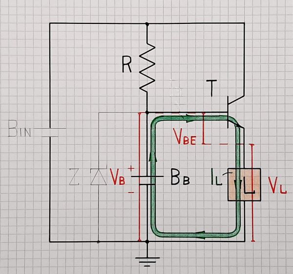
Fig. 6. The charged battery supplies the load directly through the base-emitter junction.
Conclusion
In this story, I have shown how another simple 1-transistor circuit is "invented". This is an example of how chance can help us come up with a new idea and its implementation.
This is also an illustration of the inventive "principle of combination" - two functions are combined in one transistor (regulation and switching) and two things in one battery (reference voltage source and backup battery).

1 comment thread