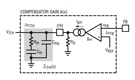
Type II compensation network for a non-ideal transconductance amplifier
I am designing a DC/DC converter in the control loop of which a transconductance amplifier (OTA) is used. This part of circuit looks like this:
To determine the needed characteristics, I am using a transfer function provided by the manufacturer (AD). However, today I decided to check the transfer function by hand and encountered a roadblock.
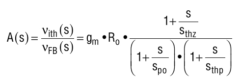
The manufacturer (and other sources) say that the transfer function is:
where:
-
s_thz = 1/(Rth*Cth), zero contributed by the resistor -
s_po = 1/(Ro*Cth), pole contributed by the op-amp input resistance andCth -
s_thp = 1/(Rth*Cthp), high-frequency pole contributed by theCthpcapacitor
I could derive the transfer function for the network of Cth, Rth and Cthp with no issue. I observe the high-frequency pole, a zero and a pole at origin typical of those configurations.
However, as the application note discussing compensation networks points out, the OTA is not ideal and so its impedance wil move the pole off of the origin. It is still a low- frequency pole, but the 'pole at origin' model becomes inaccurate.
This is where I encounter my issue. The transfer function provided by the manufacturer is very clean. However, when I add the OTA output impedance, my transfer function grows in size. The poles are no longer a simple fraction, but rather incorporate every component of the compensator.
This does make sense to me (after all, the OTA impedance 'sees' the whole network and not only one capacitor). Furthermore, the manufacturer also mentions simplifying the transfer function as well.
However, I cannot find a full derivation of the type II compensator anywhere on the internet. So, keeping the above in mind, my questions are:
- What is the accurate transfer function for this circuit?
- Why can we calculate the influence of the output impedance taking only the Cth capacitor into account?
I would appreciate any help with this question as I have been wrestling with this transfer function for a while now.
1 answer
You can use various methods for it, one way would be to simply use the ideal transfer function and make it in parallel with $R_o$:
$$\begin{align} A(s)&=R_{th}+\dfrac{1}{sC_{th}} \tag{1} \\ B(s)&=A(s)||C_{thp} \\ {}&=\dfrac{1}{\dfrac{1}{R_{th}+\dfrac{1}{sC_{th}}}+sC_{thp}} \\ {}&=\dfrac{1}{sC_{thp}}\dfrac{s+\dfrac{1}{R_{th}C_{th}}}{s+\dfrac{1}{R_{th}(C_{th}||C_{thp})}} \tag{2} \\ H(s)&=B(s)||R_o \\ {}&=\dfrac{1}{C_{thp}}\dfrac{s+\dfrac{1}{R_{th}C_{th}}}{s^2+\left[\dfrac{1}{R_oC_{thp}}+\dfrac{1}{R_{th}(C_{th}||C_{thp})}\right]s+\dfrac{1}{R_oR_{th}C_{th}C_{thp}}} \tag{3} \end{align}$$
(2) would be the ideal transfer function, with the perfect zero at DC, while (3) is the final transfer function, as derived. Note that you are not using the correct poles/zeroes, and in their paper they are using $\dfrac{1}{R_{th}C_{th}}$ for $s_{po}$, but that's before adding the rest, so some modifications are needed. To test it, use your preferred SPICE, or whatever mathematical solver. I used the modified transfer function for the paper equivalent, while for the derived t.f. I used the more compact version (it's the same, you can verify it):
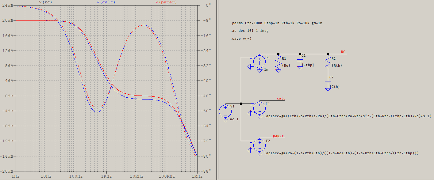
The values are bogus but the results are what matter: the traces are very close. They should be overlapping, I'll check it again later, but even if they don't, they come very close, particularly since what really matters is the phase.
As for calculating the output impedance, it depends on the values of the elements but, no, only $C_{th}$ is not enough. The most simple reason is that $C_{th}$ is used to calculate both a pole ($C_{th}||C_{thp}$) and a zero (and this disregarding the series $R_{th}$), therefore the whole response changes. So you have to consider the whole transfer function, but it should be (fairly) easier since it's a transconductance, therefore a function of current and voltage.
1 comment thread

0 comment threads