Select resistor for a diode
Suppose we have this circuit
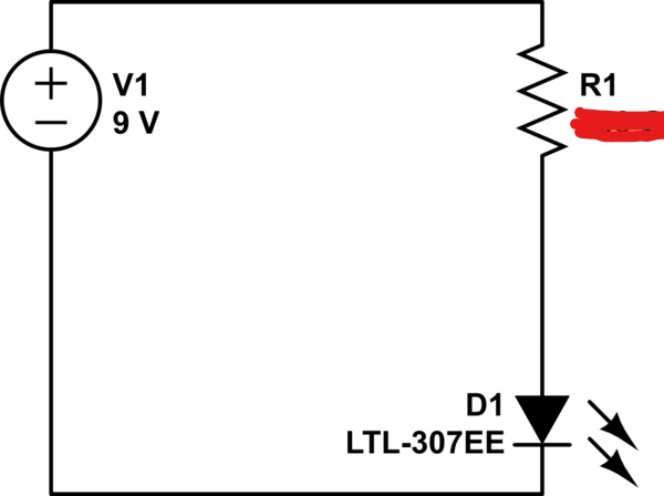
How do I pick a appropriate value for the resistor R1?
3 answers
You are accessing this answer with a direct link, so it's being shown above all other answers regardless of its score. You can return to the normal view.
You start by checking the forward voltage and rated current for the LED. 20mA is the usual industry standard for regular LEDs and the forward voltage will be specified for that rated current.
In this case the datasheet says VF = 2.0V typical @ 20mA.
So now we know the current and the voltage will be supply voltage minus forward voltage. Applying Ohm's Law, we get:
R = (Vsupply - Vforward) / I
In this case R1 = (9 - 2) / (20*10-3) = 350 ohm.
What the "appropriate" value of R1 is depends on what you are trying to achieve, which you haven't told us. Will this device be used in bright light, like outdoors, and the LED therefore needs to be as bright as possible? Is it an illumination source? Is it just an indicator, and it only needs to be bright enough to be obviously on under typical office illumination? Is it battery powered, and power conservation is a high priority? Specifications like this are important.
In any case, it would be good to know what the minimum allowable R1 is, even if you then derate heavily from there. To do that, we need to know three things:
- What the maximum allowed continuous current thru the LED is.
- What the minimum voltage drop of the LED is a this current.
- What the maximum power supply voltage can be.
In other words, we want to calculate the minimum resistance that keeps the LED operating within spec under the combination of worst case conditions.
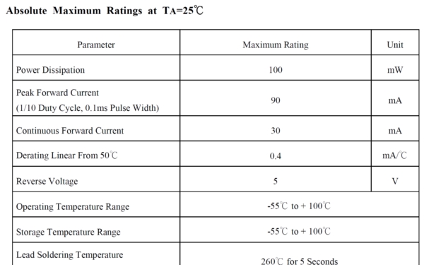
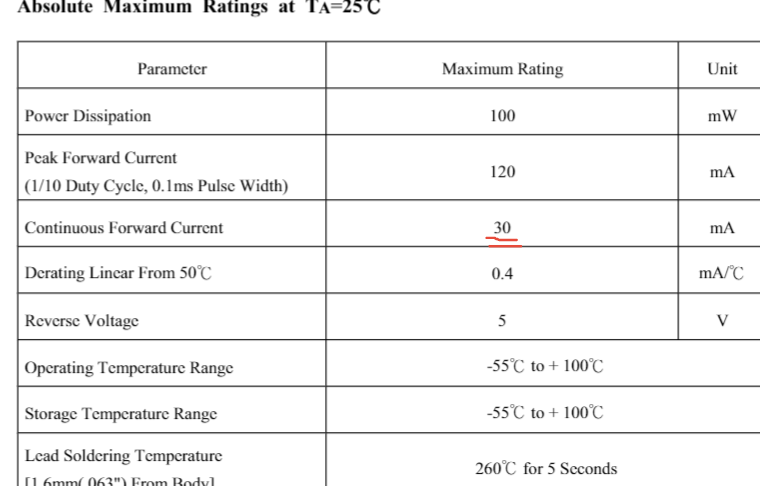
This first thing we do is look at the LED datasheet. Unfortunately, as is all too common, particularly with far-east manufacturers, the datasheet doesn't actually tell us everything we want to know. There are two tables with parameters:
and
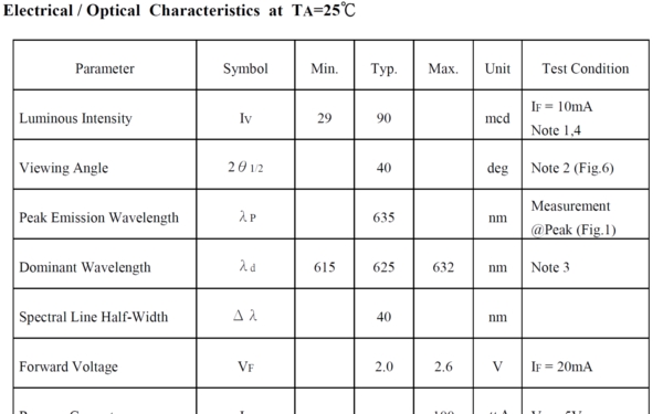
The first is Absolute Maximum Ratings, which generally means these are the limits you must never exceed. This does NOT imply normal operating values. The second table appears to be the normal operating parameters. These are the values you can actually design your circuit to.
So what maximum forward current can the circuit allow indefinitely? It's not totally clear. The first table does show the continuous forward current to be 30 mA, so that would appear to be the answer at first glance. Note that the 30 mA figure only applies to 50 °C or less. Is that die temperature or ambient? If die temperature, then it might easily be exceeded even at 25 °C ambient. This is a rather poorly written datasheet. If you want to push limits, you either need to talk to the manufacturer, or use an LED from someone that gives you proper specs.
We see later on page 4 that there is a graph showing allowed forward current as a function of ambient temperature, with 30 mA allowed up to 50 °C. 30 mA should therefore be OK if this device is specified for office use, like 25 °C. If it will be in a metal box mounted to a light pole in Phoenix Arizona, than 30 mA is clearly not allowed. For now, let's assume an office environment and go with 30 mA to at least see where we're at.
Now for the forward voltage. Here we want to know the least it can be, because that results in the most current, given the fixed power supply voltage. Here is another problem with this datasheet. We are only given a typical forward voltage, not minimum. About half the time the voltage will be 2.0 V or higher. The other half the time, it will be lower. But wait! Note that's at only 20 mA, not the 30 mA the other table says it's OK to use continuously. Hmm, they give us specs at 20 mA, but not 30 mA. That's a hint they don't really consider this LED intended for 30 mA operation.
Given all that, I consider it irresponsible to design a production circuit with just a dropping resistor using this LED at 30 mA continuously. If I needed the extra light, I'd actively control the current, or use a different LED, or possibly multiple LEDs. After all, we have plenty of voltage to run more LEDs without using any more power.
Let's assume the 9 V supply is reasonably well regulated. Since this LED can probably be run up to 30 mA, using 20 mA and the typical voltage drop for 20 mA should be OK.
You want the resistor to drop the supply voltage minus the LED voltage at the desired current. Using Ohm's law:
R1 = (9.0 V - 2.0 V) / 20 mA = 350 Ω
Since we've already accounted for some slop, you could use that resistance or higher. The nearest common value at or above this is 360 Ω. Assuming 1% parts, that could result in a resistance as low as 356 Ω
Now we look at the power the resistor will dissipate:
(7 V)2 / 356 Ω = 138 mW
Note that this is more than the ⅛ W the typical 0805 resistor is rated for.
Rarely do you need full brightness. If this is for something like office use, then 20 mA is not only excessive, but may even be annoyingly bright. 5 mA is probably all you really need, but that depends on requirements you haven't told us.
So, my answer is 1.3 kΩ.
If you really cared about maximum brightness, you wouldn't be using such a poor and wasteful circuit for driving the LED.
0 comment threads
A diode obeys the Shockley diode equation and for this circuit we have:

The current through the diode must not pass a limit so for LTL-307EE we go to the datasheet to find the maximum current before the diode is destroyed:
For the LTL-307EE at 20C we have 10^4 A Isat and Vth=0.026V

(30mA).
Now in order to find the resistance we find the resistance of the resistor if max current was flowing through the diode
If we solve this equation we get:

Hope this helps
2 comment threads

0 comment threads