Where do currents flow in circuits?
Need to visualize currents
I have long understood that one of the most important techniques to understand circuits is to see where currents flow inside them (in circuit theory, this is considered unimportant and, at best, currents are represented by small arrows with arbitrary direction).
The problem is that currents, like other electrical quantities, are invisible... and to show them, we have to visualize their paths, directions and magnitudes.
First ideas
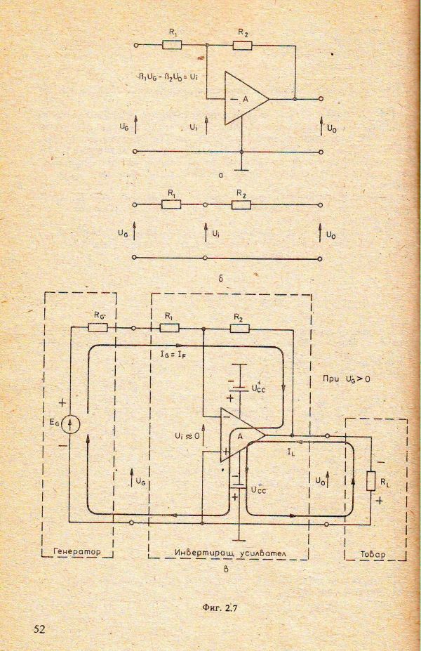
That is why, in the late 80's, for the purposes of true understanding, I began representing current paths on circuit diagrams through closed directed lines (loops). An example is the circuit diagram of an op-amp inverting amplifier from my Student Manual for the Analog Circuitry (1989):
Another electrical "law"
Even then, I realized how important is to draw power supplies because currents start from the positive terminal of the power supply and return at its negative terminal; thus each current returns to where it started. I joke with my students that this is another (topological) electrical law, after Ohm's and Kirchhoff's law, that is called Cyril's law:-)
Sophisticated current pictures
Later, I took advantage of Corel Draw to show more sophisticated current pictures where the current paths were colored in green (in association with water flow). See, for example, the circuit of an AC transistor amplifier (I made it in the late 90's):
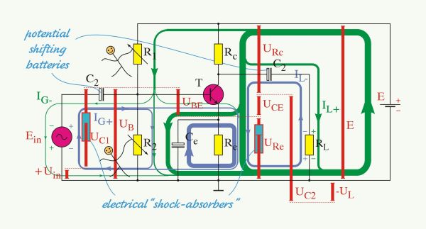
Actually, two current pictures are superimposed on the circuit - the one in blue (when the input voltage is positive), and the other in green (when the input voltage is negative).
"Live" currents
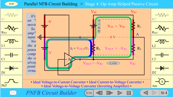
In 2000, I even made Flash animated circuit tutorials with "living"currents that were changing their thickness proportionally to the current magnitude (you need Ruffle Flash emulator to see this movie because Adobe Flash player is no longer supported).
The content is more important than form
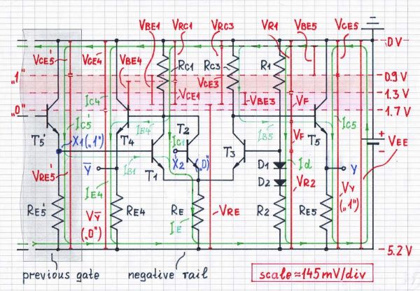
In the end, I came to the conclusion that content was more important than form... and I began to draw circuit diagrams with superimposed current pictures by hand. Here is such a "geometrical" representation of an ECL logic gate (I drew it in 2006, by color fiber pens on a white sheet of paper):
Helping the online learning
That was a long time ago... but a year ago, when we switched to online learning, I started using the ZOOM pen to draw currents on my and others' web circuit diagrams. This turned out to be a very powerful didactic technique that I managed to improve even more on the last exercise. I will show you how this happened at the final part of the last exercise on Semiconductor Devices with group 48a, ITI, FCST of Technical University of Sofia. I make full video recordings of ZOOM meetings with my students and, with their permission, I will use a link to the latest record (in Bulgarian).
The record
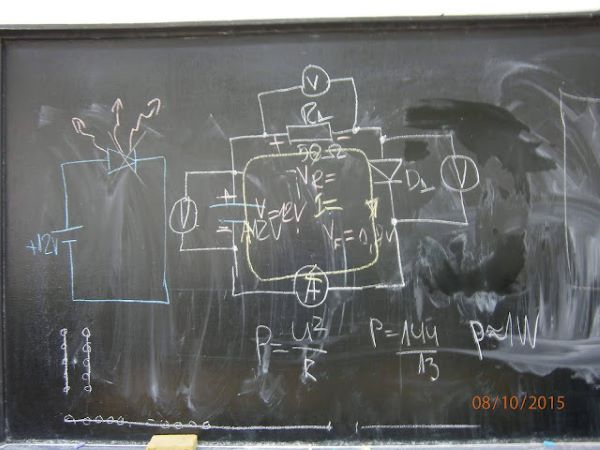
At the beginning of the video, we started discussing the circuit diagram for "static" diode measurement. For this purpose, I put an old picture drawn on the blackboard in 2015… and we began discussing why a resistor was needed... and what would happen if it was not there. It took us almost 7 minutes during which we were looking at all kinds of resources on the web...
Then it was time to "implement" our conceptual design on a solderless prototyping board. I again used a photo (attached below) of the "good old real learning", in which the power supply and meters were outside the picture. It occurred to me to ask the students where and what measuring devices are… and then a "brilliant" idea came to me to draw the current path over the picture accompanying it with explanations.
I guess you will be interested to see how I did it; that is why I translated the video above in the interval from 6:30 min to 16:00 min:
6:30 min: … So, this is the circuit - a voltage source, resistor and diode in series. Let's now see how this circuit was made on the prototype board by your colleagues years ago:
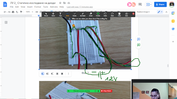
Some elements are not seen here as a kind of mystery and this allows me to ask you about them. For example, what are these two black wires at the bottom of the board? Or what are these pairs of black and red wires on the left and right? Where is the studied circuit? This is what your colleagues have done... They tested... what? Apparently they tested an LED... and to limit the current through it, they included a resistor… And the interesting thing now is to see where the current flows…
OK, let me ask again, "Does anyone understand what these two wires are - black and red, on the right?
Student: "These are the probes of a meter...and the black wires below are of the power supply…”. Exactly! These on the right are hand-made probes of a meter. As you can see, they have sharp tips and are inserted directly into the holes of the board. So this is one meter and this is the other meter. Now it remains to specify what each of the meters is.
Student: "I guess the one on the right is an ammeter because it's connected in series." Exactly! Let's see who said this wisdom. Let everyone turn on their cameras. Who said that? Dimitar?
Student: "Yes." Exactly; the right is the ammeter and the left is obviously the voltmeter because it is connected in parallel to the LED. So, what we are going to do now is to outline the trajectory of the current... I propose to color it green (association with water flow). We said that a current can travel on very complicated roads, but in the end it returns to where it started (each current returns to where it came from). If you don't know, this is the third electrical law - Cyril's law, formulated after Ohm's and Kirchhoff's laws (of course, this was only a humor:-) Note this is a “topological” law.
9:30 min: Let's see this in practice now. Look again at the black wires at the bottom of the board. They are thinner and one of them is wrapped in red tape.
Student: "This should be the voltage source with its two terminals - "plus" and "minus"... the red one is the "plus"". Exactly! This is the power supply... the "adapter", as they say… I marked it with this red tape to mean it is "+". Now I will draw it with the Zoom pen as simple as a battery.
And how to draw (conceptually) the ammeter? What is inside its two probes? Short circuit... this is the ammeter… And what about the voltmeter? There is nothing between its red and black probes. So, this is the circuit…
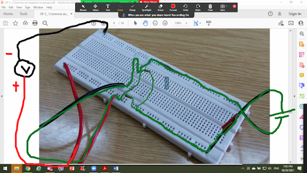
11:00 min: Now let's just mark the polarity of the 12 V voltage source (power supply) with "+" and "-" in red… and we are ready. We are the current (in green) and we start moving from the positive terminal of the source towards its negative terminal. Who will take part? Let someone else now. You just have to guide me... I am like a little car and you have to tell me where to go. So, I start from "+" on the right black wire (marked in red) and reach the board. Where should I keep moving? I ask to find out if you know how the connections on the board are.
Student: "Towards the resistor ..." Towards the resistor... Good! So all these contact holes are connected to each other like one (positive) rail... and I travel on it. I get to the resistor and what do I do? I go up to its right lead... enter the resistor... go out of its left lead... go down… and step on the junction of 5 holes on the board. I come to the red cable and what to do now? Where to go - left, straight... or somewhere else? Let me remind you that this on the right was an ammeter which was a short circuit.
Hmmm... a very fun and instructive "game" this is. This is how things are understood - not through dry formulas and definitions... not through "reading" lectures and performing boring exercises like "do this and that"...
12:55 min: Student: "So the current should go through the ammeter?" Very well, so I am the current... and what am I going to do? I will get on (Student: "on the red cable")... That is right; I am a clever being and I choose the smallest obstacle (as a student who wants to pass the exam :-) So I am going to travel along the red cable... I go into the ammeter... then go inside through its shunt which has almost zero resistance (a piece of wire when it is in the 10 A range)... and I go out through its black cable. I get off the board... move on the junction... reach the red cable ... and what do I do now? Am I getting on the red cable?
Student: “Yes…” Think about it…
Another student: "The current is branching...and on the red cable..."
13:50 min: Think again ... Here on the left is a voltmeter; let's draw it - this is its black cable and this is the red one. But what was a voltmeter? How did we explain it to our hypothetical students last time? Is current flowing through it? Does it make a current path? Or just the opposite?
Students: “No… no…” It has infinitely high resistance, which, in simple human language, means that there is nothing here... nothing… open circuit… So the current can't go through "nothing"... and then, where does it go? Where does it find a path to go?
15:00 min: Student: Through the LED?" Exactly! Who said it to put it on the list? So it goes up through the right LED end... goes inside... through the PN junction and makes it glow... goes down through the right LED end on the board... moves along the negative rail (not towards the black voltmeter cable)... and finally goes back on the black cable to the negative terminal of the power supply… The current returned to where it started...
16:00 min: This was the full path of the current drawn on the picture of a real circuit. It is not beautiful... we are interpreting it at the moment... but the important thing is that we understand it...
Then, until 23:30 min, we investigated another "current excursion" where we saw how the current branches when meeting a current divider:
It will be interesting for me to know your opinion about this didactic technique.
See also
What are voltages in circuits? (voltage bars)
What are voltages inside resistors? (voltage diagram)
Web Resources
How to Visualize Currents in Circuits (Circuit Idea wikibook)

0 comment threads