How to calculate the RC filter of a TCXO for a RFIC reference?
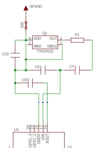
I have a 30MHz TCXO circuit (TCXO datasheet) like this serving as local oscillator to a RFIC:
The RFIC manufacturer recommends to "add filtering caps" for high RF output cases. That is >20dBm, after which I suppose they are concerned that the fundamental signal radiates back into the oscillator traces. Specifically, one AN says:
in the high output power cases (+20 dBm or higher), it is recommended to use additional filtering sections in order to achieve larger suppression at the reference spurs. These additional filter sections contain a grounding capacitor to the XOUT and an RC filter from the TCXO output to the input of XIN. It only makes sense when the goal is to comply with the ETSI Category 1 EMC regulation within acceptable margins.
I do need this ETSI Category 1 (they mean EN/ETSI 300 220-1 for sub-GHz short range devices) which specifies certain limits on blocking, minimum adjacent channel selectivity, spurious response rejection and so on.
They say that component values should be chosen based on frequency band, which I assume means a suitable cut-off frequency for the RF carrier. They call this a "RC filter" although it isn't a conventional low pass circuit with a single cap to ground, in which case I'd just do 1/2πRC.
Questions:
- How do I pick the values of R1 and C7 given a certain cut-off frequency (say for example 500MHz)?
- What is the purpose of C7, is actually part of the filter or is it only there for blocking purposes? Why isn't it sitting towards ground?
I'm assuming C6 and C8 are just load caps for the oscillator and should be 10pF or so.
1 answer
The RFIC manufacturer recommends to "add filtering caps" for high RF output cases.
It seems your questions are really about this RF IC, not the oscillator. The oscillator itself seems to be pretty straight forward. You apply power and an accurate frequency comes out, which is 30 MHz in your case. Some versions of this oscillator have a control input that can tweak the output frequency a bit as a function of the control voltage, but you are not using that type. You have a three-terminal device: Power, Ground, and output (although in your case there are two ground pins).
Without the RFIC datasheet, it's not clear what "high RF output" means. Is that high frequency, high power, or something else?
They say that component values should be chosen based on frequency band, which I assume means a suitable cut-off frequency for the RF carrier.
Again, this is about the RFIC, not the oscillator. Most likely, they want the capacitors smaller at higher frequencies. Put another way, they want their impedances to be about the same regardless of what frequency you use.
It's also not clear what this has to do with the carrier. You say this TCXO if for the local oscillator. That might mean the IF, or maybe something that goes thru a PLL/divider chain to make the actual carrier from.
How do I pick the values of R1 and C7 given a certain cut-off frequency (say for example 500MHz)?
You haven't given us enough information to answer that. The place to look would be the RFIC datasheet.
Just guessing, it looks like R1 works against the series combination of C7 and C8 to form a low pass filter. That is probably to attenuate the harmonics of the TXCO output. The capacitance of this RC filter is split into two pieces so that there is a tap for an attenuated versions of the filtered TXCO output. That's just a guess from looking only at the circuit you show.
What is the purpose of C7, is actually part of the filter or is it only there for blocking purposes? Why isn't it sitting towards ground?
Again, the circuit you show is dictated by the RFIC, not the TXCO. Look at the detailed description of the XIN input of the RFIC. My guess is that C7 is primarily there to block DC. C7 and C6 form a voltage divider. Whoever created that circuit seemed to think that the output of the TXCO needs to be attenuated before being fed into the XIN input of the RFIC. Only the RFIC datasheet can provide the parameters of the XIN input.
The part that I find most curious is C8. It is directly between XOUT and ground. Perhaps this would make sense after a careful read of the RFIC datasheet.

2 comment threads