Post History
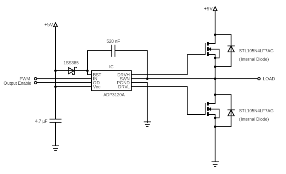
My goal is to make an RC car, and I have a couple of questions regarding driving the brushed DC motor. Schematic for half of my H-bridge looks like this for now (it will be identical on the other s...
#1: Initial revision
H-Bridge components and calculations
My goal is to make an RC car, and I have a couple of questions regarding driving the brushed DC motor. Schematic for half of my H-bridge looks like this for now (it will be identical on the other side):  I am trying to make a H-Bridge circuit to drive a brushed DC motor ([Motor_Datasheet](https://asset.conrad.com/media10/add/160267/c1/-/en/001385115DS01/scheda-tecnica-1385115-motore-540er-reely-parte-di-ricambio-532114c.pdf)). It will be powered by two 18650 cells in series. I have decided to use 4 N-channel MOSFETs ([Mosfet_datasheet](https://cz.mouser.com/datasheet/2/389/stl105n4lf7ag-1850880.pdf)). There are a couple of things I am not sure about. Firstly, is this calculation for power dissipation correct? The first part is the conductive loss, that part I'm pretty sure is right. The second part concerning the switching losses is something I still do not fully understand, so some links to articles or short explanation of why it is in/correct would be appreciated. P = (I^2 * R) + (I * V * (t_on+t_off)/2 * f) = 0.517 W Where: **I** is the expected average current (10A), **R** is the drain-source on resistance (4.5 mOhm), **V** is the voltage of fully charged batteries (9V), **t_on** is calculated from the datasheet as t_don + t_r = 16.5 nS, **t_off** is calculated from the datasheet as t_doff + t_f = 58 nS, and **f** is the PWM frequency (20 kHz). Another question is: Can this H-bridge be driven by two ADP3120A (ADP3110A) dual bootstrapped MOSFET drivers ([Driver Datasheet](https://www.mouser.com/datasheet/2/308/ADP3120A_D-2309800.pdf)). The MOSFET's input capacitance is typically 1500 pF, and the driver should be able to drive 3000 pF load. The difference between the ADP3120A and ADP3110A is that the first one has 45 nS propagation delay and a 25 nS transition time. The propagation delay of second one is 25 nS and transition time is 30 nS. How can these values be used to choose the right one? Last thing: The Vcc to the ADP3120A should be >=5V. I want to use the 5V that will be used to power the MCU. But using higher voltages is preferred, according to the datasheet. Would it be possible to drive it from the same source as the motor? Or would powering it from two 18650 cells in series be a problem since the voltage will go from 9V (probably less) to approximately to 6.4V. Is the change in Vcc of the driver during operation something to avoid?


