pH Electrode Buffer - Offset when solution grounded
Problem
pH electrode buffer offset appears when solution is grounded.
Detail
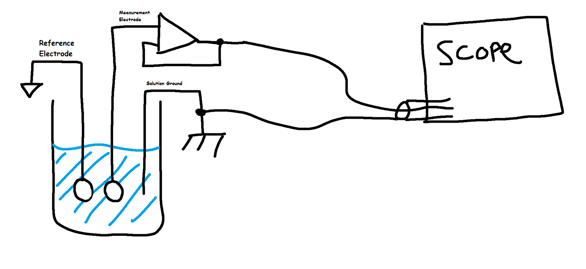
I have a pH electrode in some conductive solution (~1000uS). The output (measurement electrode) is buffered by an electrometer type opamp. The opamp rails are powered by an LDO (+/- 3.3V) which in turn are powered from a USB cable to my PC. The reference electrode is referenced to ground, which is shared between USB ground and PE through oscilloscope probe.
The board has been cleaned (ultrasonically in isopropanol and then baked for an hour). The pH electrode has a measurement glass impedance of ~250 MegaOhm and the liquid junction an impedance of around 10 kOhm.
If I measure the pH of liquid in a glass jar the output is relatively stable (<10 mV). However, when I place a grounded (PE) wire in the liquid a negative offset ranging between 50-200mV is introduced. Even if I float the oscilloscope I see the same offsets.
Isolating the buffer circuit solves the issue - but I am trying to understand why the offset happens.
The setup looks something like this (power supplies not show):
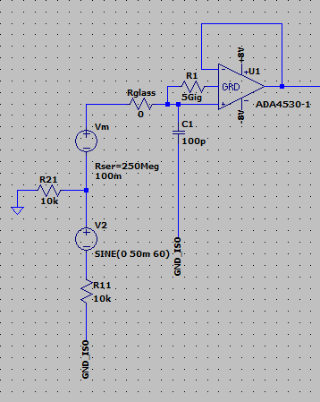
I tried to model the power supply (https://cutt.ly/nVuMekg) but I don't see the same offsets. I see 60Hz noise coupled through parasitic capacitance in my isolation transformer (60Hz noise is also present in real circuit but filtered by low pass).
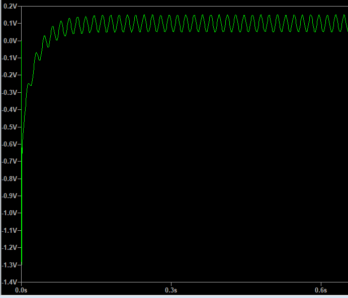
Simulating with common mode noise (to replicate a ground loop) shows considerable 60Hz noise on the output of the buffer but no DC offset. I notice that the output of the buffer is not very stable (very low frequency noise - <<1Hz) when PE is connected to the solution.
Simulation:
Output:
2 answers
DC offsets in hundreds of mV from different grounds may be coming from either the floating ground or the PE earth. The latter may be from rectified AC line filter noise shunted to PE. The former might be caused by front-end ESD protection diode rectification with DC bias and a CM signal large enough to cause DC leakage from any AC stray field (V/m) coupled by air capacitance which then can be rectified somewhat.
Other info
Sensing high impedance signals with a different ground unbalances the signal and also creates a differential error. Remember ground by definition is 0V only at that location but loosely extended if you follow guidelines to prevent measurement or detection errors. This rule applies to all grounds incl. a floating battery and PE ground.
In medical ECG, EEG high impedance signals achieve high SNR using common mode feedback to the shield also called "Guarding" when using a loop around traces or via's to reduce crosstalk. Another method is to use the common mode sense signal to create a virtual ground (=0V by definition) on the body and is standardized as the RLD or "right leg drive" signal.
Also 120 dB CMRR INA INstrument Amplifiers IC's are mandatory and only degraded by the cables and probes due to differences in capacitance to ground imbalance. A common design also uses EMI filter capacitor values for AM and grid rejection when used with noise filters. If these were 10% tolerance caps to the CM node, they would degrade the CMRR so the value must be reduced to lower sensitivity and preferably using 1% C0G caps.
Perhaps CM grid noise including AM radio is being rectified by the ESD protection diodes to create this offset. These might not be included in your simulation and may be imperfectly matched from process tolerances.
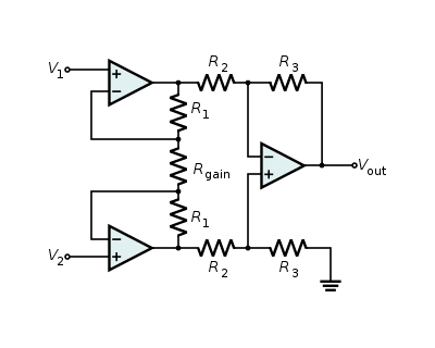
You should never use a single Op Amp buffer as you did to measure high impedance. rather 3 Op Amps in an INA configuration or a real INA IC. The sensor wires must be shielded twisted-pair (STP cable) for best results.
0 comment threads
It seems you have ground loops, and possibly having multiple ground connections shorting out your signals. Your hand-sketched diagram is a good start, but you need to show all the ground connections.
The scope is presumably grounded via its ground lug that plugs into the electrical outlet. Let's call that the "power ground". You show that with the chassis ground symbol in your diagram. But then what's the ground connected to the reference electrode really connected to? Using a different symbol means it's not the same as the power ground, but what is it?
You mentioned that the opamp is powered from a power supply derived from a computer's USB. That is also most likely referenced to power ground. Show that in your diagram.
I'm not familiar with the details of pH meters, so don't know what the significance of the reference electrode is. You don't seem to be using the output of the reference electrode, so it appears it's job is to float the solution at some voltage. However, you also show an explicit connection between the solution and power ground. Something is wrong here.
I would start by eliminating ground loops. Make sure your whole setup is referenced to ground by exactly one path. That should probably be your scope ground lead, since that's the hardest to avoid not being connected to ground.
Use batteries to power the opamp. Not only do they inherently float, but they will also be much less noisy than something derived from USB power.
I can't say what to do about the reference electrode since I don't understand what its function is supposed to be.
I understand the concept of a ground loop - but I don't understand why it creates a DC offset.
It is possible that the multiple ground connections are shorting your reference cell. It's not clear from your diagram, but is hinted at.
1 comment thread

3 comment threads