How to change the polarity of an input using a single switch?
I have an mcu pin and I want to sense a voltage up to 24V to 36V.
I want to connect some outputs on the board I'm designing and I don't know whether those outputs will provide a voltage or will be open collector outputs.
Also, some outputs will be just relays and the other terminal will be at GND or just at the main voltage (supply rail). For this reason, I want to provide some selections like switches or jumpers to give the ability in the circuit to be modified.
Example below:
To be able to connect an mcu to a high voltage I'm using a simple level translator.
This can be done with a simple NPN.
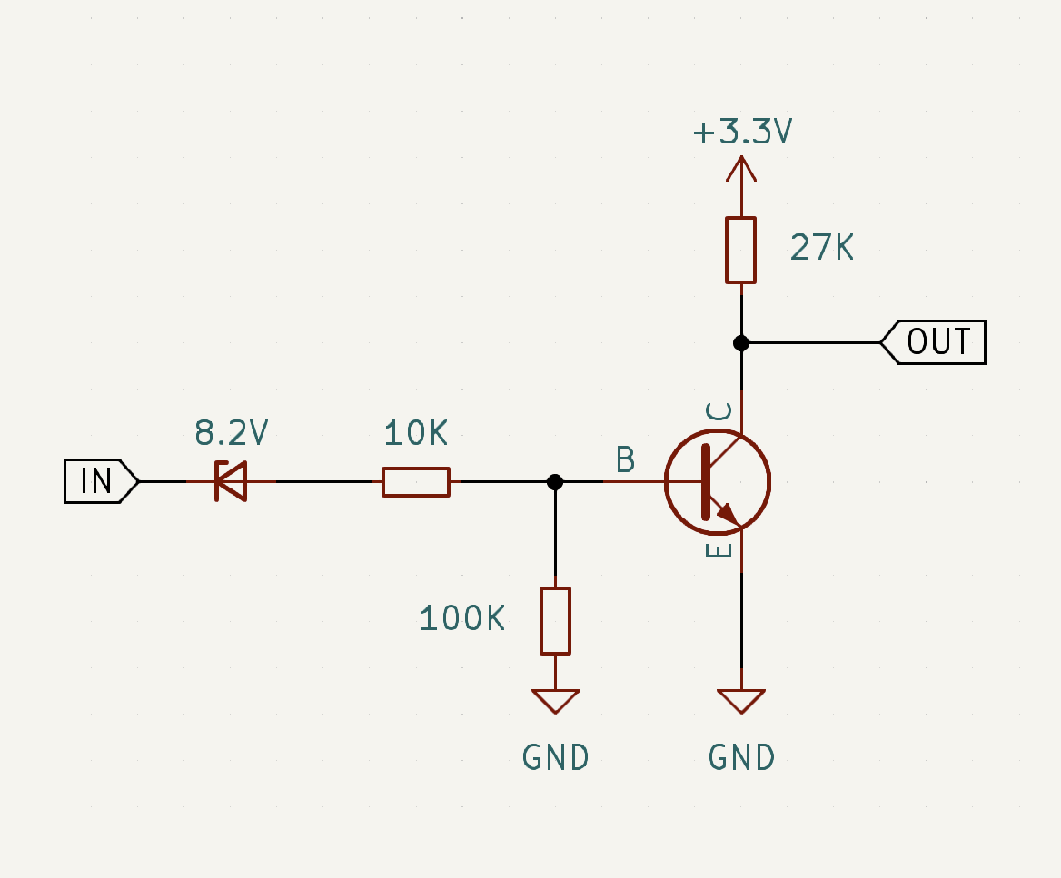
This circuit gives me the following output:
LOW: For any voltage above 8.2V
HIGH: When the line is floating or when the line is grounded.
I want to add a switch or a jumper to modify this circuit on the fly and change its behaviour as following:
LOW: When the line is grounded.
HIGH: For any voltage above 8.2V or when the line is floating.
Note: voltage below 8.2V is considered as "input is floating".
This is the truth table.
For simplicity we will asume that voltage means +24V DC
| Selection | Voltage | Floating | Ground |
|---|---|---|---|
| Option 1 | LOW | HIGH | HIGH |
| Option 2 | HIGH | HIGH | LOW |
1 answer
The following users marked this post as Works for me:
| User | Comment | Date |
|---|---|---|
| DeadMouse |
Thread: Works for me Thanks! That's helpful |
Jun 17, 2023 at 16:01 |
The difference between your two options is which polarity the input floats to when left open, and whether there is an overall inversion.
Adding the inversion in the firmware would require one more pin from the chip.
Not necessarily. I was envisioning inversion or not would be specified by configuration data stored in non-volatile memory. This is how PLCs do it. Physical switches are rather klunky.
Assuming you really want to do it the klunky way, I'd separate how the line floats from adding the inversion.
The inversion part is simple. You already have a digital signal at the collector of the transistor. Running that thru a XOR gate before presenting it to the micro allows for optional inversion.
Adding an optional pullup to the input changes the voltage at which the line floats. 100 kΩ to 24 V at IN is enough to easily turn on the transistor.
Now the question is how to add the pullup and change the level of the second XOR gate input with a single jumper or switch. Have the switch either connect a node to 24 V or not. That works directly for the pullup. A resistor divider from there to the XOR gate can change the 0-24 V into 0-3.3 V. For example, 100 kΩ pullup with 16 kΩ to ground would work.
One last issue is that you don't want high voltage on the input back-driving the pullup node and changing the polarity of the XOR input. The solution is to isolate each with a diode:

1 comment thread