Choosing between common-drain JFET amplifier, and common-source
Do common-source JFET amplifiers have an advantage over common-drain? The JFET would be in a low noise photodiode amplifier. The signal is 100us pulses with 10us raise times.
Here are the schematics which I have in mind.
The op-amp would be LTC6252 or LT6200. Single-supply operation is desirable for me.
Common-drain
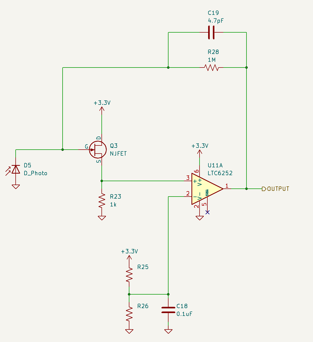
Common-drain JFET has a prototyping appeal, because it would be easy to try a simple transimpedance op-amp (without a JFET) on the same PCB. Fallback position.
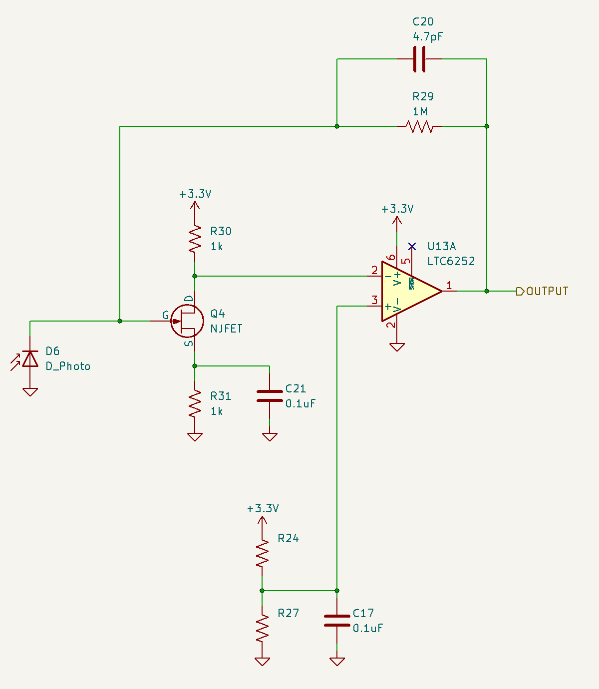
Common-source
1 answer
The first circuit uses the FET in follower mode. That means it works as an impedance buffer with a gain a little below 1. Such configuration can be useful to turn a high impedance signal into a low impedance signal.
The second circuit uses the FET as a common source amplifier. This inverts the signal. It also has the possibility to provide voltage gain. It doesn't in this case at DC since R30 and R31 have the same value. However, due to C21 there will be voltage gain at higher frequencies. The rolloff frequency for R31 and C21 is 1.6 kHz. Below that, the gain is roughly flat and a little less than 1. Above 1.6 kHz, the gain increases with frequency until signals get clipped due to the voltage range that can appear across R30.
However, both circuits are questionable at best. There are two ways to use a photodiode, in forward voltage mode, or in reverse leakage mode. These circuits do neither. I'll refer to your top circuit:
Note: This is the original schematic. The schematic in the question has been changed since this answer was written.
Q3 is just a buffer. It will attenuate the signal from the photodiode slightly, and it will also add an offset. I don't see much advantage to either since the opamp input is high impedance. The voltage setpoint across the diode would also be more predictable with Q3 and R23 removed (diode connected directly to inverting opamp input). Let's proceed as if this is the case.
Due to the feedback, the opamp will try to maintain a fixed voltage across the diode. That fixed voltage is set by R25 and R26 dividing down the supply. C18 is meant to attenuate noise from the supply onto this diode driving voltage.
Since the voltage across the diode is fixed, this circuit detects changes in current thru the diode. That current must go thru R28, thereby creating a voltage signal as a function of the diode current. This is called a transimpedance amplifier.
So far so good, but forward biasing the photodiode makes no sense. The higher the bias voltage, the more current will flow thru the diode just because it acts like a diode. Any change in current due to light levels gets progressively more swamped as the driving voltage is increased.
Normally, you'd keep some fixed reverse bias across the diode, then have the transimpedance amp create a voltage as a function of the diode leakage. The leakage will change due to illumination, which is the point of a photodiode.
The other way to use a photodiode is to measure it's open circuit voltage. However, this circuit is clearly holding a fixed bias voltage across the diode and measuring its current. That's actually the preferred method for something like a photodiode, as apposed to a photocell used as a light sensor.
This circuit would make a lot more sense with the photodiode flipped around.
So in summary, start by getting rid of Q3 and R23, and connecting the diode directly to the opamp negative input. Then flip the photodiode around so that the anode is grounded and the cathode connected to the opamp.
0 comment threads

1 comment thread