Post History
I am learning IC design layouts using Cadence Virtuoso and now I got stuck with the concept of using vias. The question is when and where to use it? I am attaching the schematic of my inverter tuto...
#1: Initial revision
by
 aditya98
·
2023-10-20T22:34:21Z (over 1 year ago)
aditya98
·
2023-10-20T22:34:21Z (over 1 year ago)
When and where to use vias in an IC design layout
I am learning IC design layouts using Cadence Virtuoso and now I got stuck with the concept of using vias. The question is when and where to use it? I am attaching the schematic of my inverter tutorial 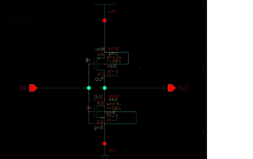 and layout 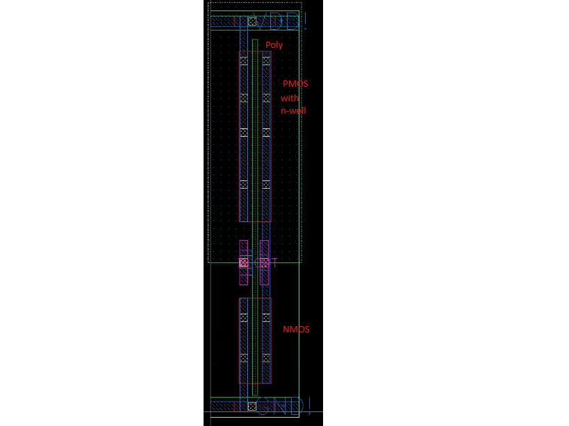. Also 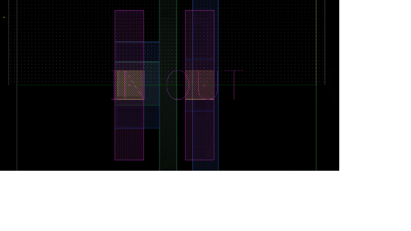here is the zoomed screenshot where vias are used for input and output pins. On the top and bottom we have Vdd and Gnd.The blue rectangle is the M1 metal layer and the purple is M2 metal layer.The dotted rectangle is the n-well which has pmos in red rectangle and in the below section we have nmos in red rectangle. The thin green rectangle which goes across the pmos and nmos is the poly. The input pin has both a contact and a via, whereas the output pin has only a via. Could you please guide me like when to use a via and where and also if there are more pins in a different design how should I analyse in having vias.