MOSFET drain current ringing in saturation region
I benchtested below 0.7A constant current source circuit and observed few cycles of oscillation on drain current. With the help of bode plot analysis , I have managed to reduce the oscillations on drain current by increasing the phase margin to some acceptable level.
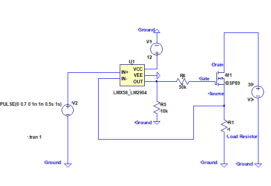
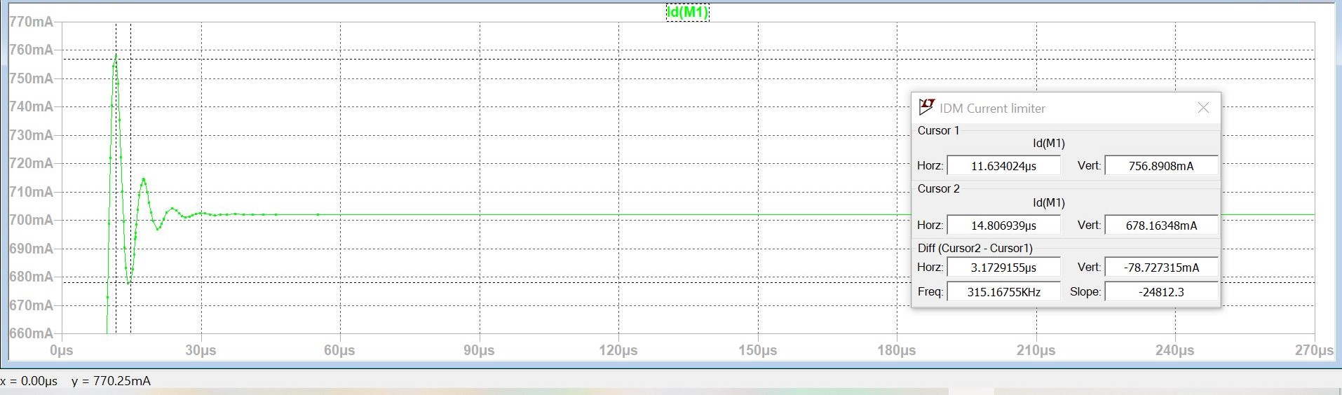
While doing the analysis , I observed in Ltspice and on the test bench that the amplitude of drain current oscillations and cycles increase as the drain voltage gets reduced from 30V to 7V.
feedback element between drain terminal and gate terminal is miller capacitance. Is miller capacitance value getting reduced due to the application of higher voltage across it like it does in ceramic caps ( Vdg = 30V -Vg) and hence stores lesser charge compared to 7V ? and due to lesser stored charge , it gets dicharged in fewer cycles ?
looking forward to the comments on this .
Thanks
2 answers
It's got nothing to do with the MOSFET's miller capacitance. Miller capacitance causes problems in common-source circuits but, your circuit is common-drain (or source follower) hence, with a steady DC voltage on the drain (your power supply), there can be no problematic feedback via the miller capacitor to the gate.
Any issues with the stability (from to a step change in demand) are due to the 50 kΩ gate resistor and the gate-source capacitance. You might say "hey, it's a source follower so gate-source capacitance doesn't come into play" and, that would be a fairly valid point should the MOSFET source follower have near unity voltage gain (like a BJT). But, it doesn't so, about 50% of the gate-source capacitance can be modelled as sitting between gate and 0 volts.
This produces a sizable extra chunk of phase lag that approaches 90° in the feedback loop and takes you close to instability. In fact, many of these types of circuit are so unstable that local feedback around the op-amp are needed to stabilize them.
Then you should ask yourself, do you really need a very fast response in load current from a demand change and, if not, then put an RC filter between demand input and non-inverting input of the op-amp.
Regarding the variation in overshoot with supply voltage, this might be because the drain-source capacitance increases as drain-source voltage decreases. That capacitance can be regarded as being in parallel with the load hence, stability changes as supply voltage changes.
1 comment thread
Your controller is too fast compared to the plant (the thing being controlled), thereby causing instability.
The most obvious culprit is the 50 kΩ resistor between the controller output and the FET gate. The resistor and the gate capacitance low pass filter the control signal, which effectively makes the FET act slow.
To fix this, stop slowing down the plant, and give yourself a way to slow down the controller as needed to attain stability. The first part is easy. Get rid of R6. Replace it with a direct connection. I frankly can't even guess what logic led you to put it there in the first place, let alone such an absurdly large value.
The easiest way to provide a means to slow down the controller is with a "compensation capacitor" around the opamp. This is a small cap from the output directly back to the negative input. This also means the negative input needs to be driven with a finite impedance for the cap to work against. That can be accomplished with a resistor in series with the feedback signal.
Here is the overall topology:
C1 is the compensation capacitor around the opamp, and R1 provides the guaranteed finite impedance for it to work against. The easiest way to find the value of C1 is by experimentation. Too low, and the system is unstable. Too high, and the response is slower than needed.
I'd drive the system with a square wave and watch the resulting step responses on R2 with a scope. Find the value of C1 where the ringing stops or is below the level you care about. Then use 50% to 100% higher value to account for part variations.
The main point is that R1-C1 should be the dominant pole around the loop. Knowing the frequency response from the gate to source of the FET is difficult, which is why you need to experiment.
Depending on the particular opamp, C1 may not be needed at all. I didn't look up your opamp, but a unity-gain stable 1 MHz gain⋅bandwidth opamp may already be slower than the FET gate to source response.
It is a good idea to leave pads for C1 anyway unless you are really tight on space. You don't have to populate C1, but it might save your butt some day when a problem is discovered with a new lot of chips, an unexpected operating point, you want to use a different opamp without respinning the board, etc.
will putting C1 provide faster feedback path for high speed changes at the op amp's output and hence stabilize it faster ?
Yes. Think of C1 as providing negative feedback of the derivative of the opamp output signal. When the opamp tries to slew rapidly, C1 causes larger negative feedback, thereby slowing the opamp response to something the plant can realize.
1 comment thread

0 comment threads