Communities

Writing
Writing
Codidact Meta
Codidact Meta
The Great Outdoors
The Great Outdoors
Photography & Video
Photography & Video
Scientific Speculation
Cooking
Cooking
Electrical Engineering
Judaism
Judaism
Languages & Linguistics
Software Development
Mathematics
Mathematics
Christianity
Christianity
Code Golf
Code Golf
Music
Music
Physics
Physics
Linux Systems
Linux Systems
Power Users
Power Users
Tabletop RPGs
Tabletop RPGs
Community Proposals
Community Proposals
tag:snake search within a tag
answers:0 unanswered questions
user:xxxx search by author id
score:0.5 posts with 0.5+ score
"snake oil" exact phrase
votes:4 posts with 4+ votes
created:<1w created < 1 week ago
post_type:xxxx type of post
Search help
Notifications
Mark all as read See all your notifications »
Q&A

Comments on MOSFET drain current ringing in saturation region

Parent

MOSFET drain current ringing in saturation region

+1
−0

I benchtested below 0.7A constant current source circuit and observed few cycles of oscillation on drain current. With the help of bode plot analysis , I have managed to reduce the oscillations on drain current by increasing the phase margin to some acceptable level.

Constant current circuit LTspice simulation

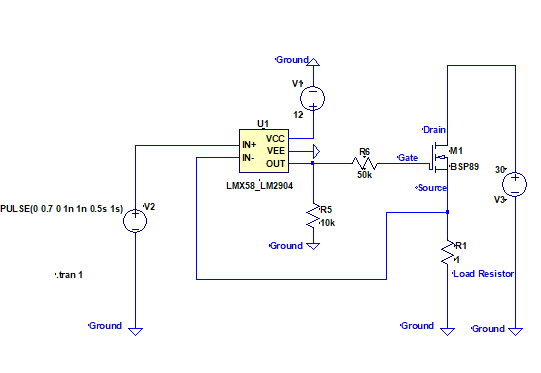
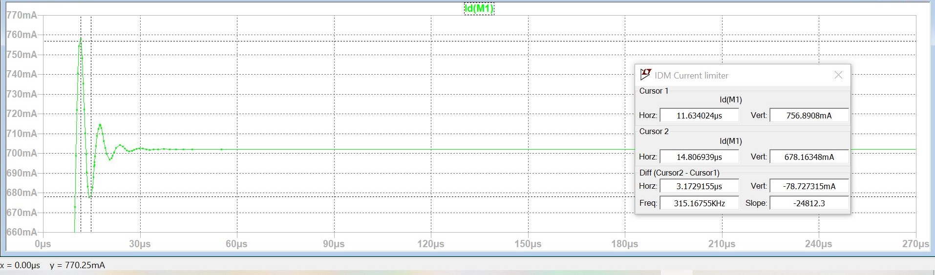
While doing the analysis , I observed in Ltspice and on the test bench that the amplitude of drain current oscillations and cycles increase as the drain voltage gets reduced from 30V to 7V.

Drain current @30V Drain voltage ripple_drain_current_max@ 30V_Vd=78mA Drain current @7V Drain voltage ripple_drain_current_max@ 7V_Vd=176mA

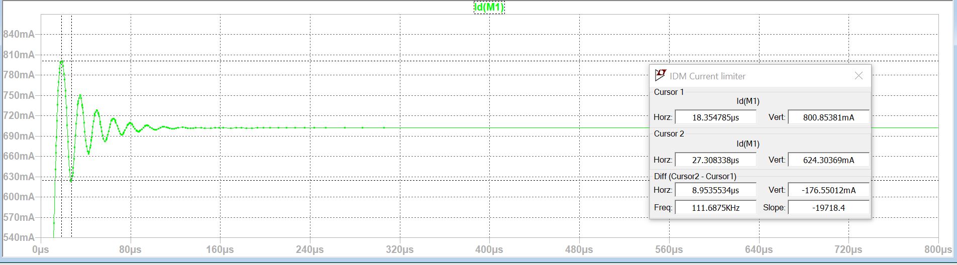
feedback element between drain terminal and gate terminal is miller capacitance. Is miller capacitance value getting reduced due to the application of higher voltage across it like it does in ceramic caps ( Vdg = 30V -Vg) and hence stores lesser charge compared to 7V ? and due to lesser stored charge , it gets dicharged in fewer cycles ?

looking forward to the comments on this .

Thanks

History
Why does this post require moderator attention?
You might want to add some details to your flag.
Why should this post be closed?

0 comment threads

Post
+3
−0

It's got nothing to do with the MOSFET's miller capacitance. Miller capacitance causes problems in common-source circuits but, your circuit is common-drain (or source follower) hence, with a steady DC voltage on the drain (your power supply), there can be no problematic feedback via the miller capacitor to the gate.

Any issues with the stability (from to a step change in demand) are due to the 50 kΩ gate resistor and the gate-source capacitance. You might say "hey, it's a source follower so gate-source capacitance doesn't come into play" and, that would be a fairly valid point should the MOSFET source follower have near unity voltage gain (like a BJT). But, it doesn't so, about 50% of the gate-source capacitance can be modelled as sitting between gate and 0 volts.

This produces a sizable extra chunk of phase lag that approaches 90° in the feedback loop and takes you close to instability. In fact, many of these types of circuit are so unstable that local feedback around the op-amp are needed to stabilize them.

Then you should ask yourself, do you really need a very fast response in load current from a demand change and, if not, then put an RC filter between demand input and non-inverting input of the op-amp.

Regarding the variation in overshoot with supply voltage, this might be because the drain-source capacitance increases as drain-source voltage decreases. That capacitance can be regarded as being in parallel with the load hence, stability changes as supply voltage changes.

History
Why does this post require moderator attention?
You might want to add some details to your flag.

1 comment thread

@#52987 Understood . putting a RC filter with cut off frequency of 100Hz would cause the phase shift ... (3 comments)
@#52987 Understood . putting a RC filter with cut off frequency of 100Hz would cause the phase shift ...
kadamrohan16‭ wrote about 2 months ago

Andy aka‭ Understood . putting a RC filter with cut off frequency of 100Hz would cause the phase shift of 90 degree roughly at 10*100Hz then do i have to make sure that the 90 degree phase shift due to RC filter happens after unity gain crossing ? in case of source follower , why only 50% of gate to source can be modelled between gate and 0 ? is it because threshold value MOSFET gate voltage is stored across the gate capcitance and rest of the voltage across load ?

Andy aka‭ wrote about 2 months ago

You have to make sure that the op-amp doesn't deliver significantly more than a 90 degrees open loop phase shift at loop gains greater than unity. Most op-amps will be fine but, if you really push things too far to get a rapid response you might come unstuck. Source followers do not have the "only one diode drop" between base and emitter hence they are flakier to rely on as a source follower. 50% is my rule of thumb in this situation.

kadamrohan16‭ wrote about 2 months ago

Andy aka‭ just to confirm ,' Demand input ' is output of op-amp ?