LED driver with feedback through light. Which feedback topology is better?
I’d like to create a stable IR LED light source. I’ve read that LED efficiency changes with temperature. I’ve seen two designs which used feedback through light to correct the LED temperature drift and aging. They used slightly different topologies.
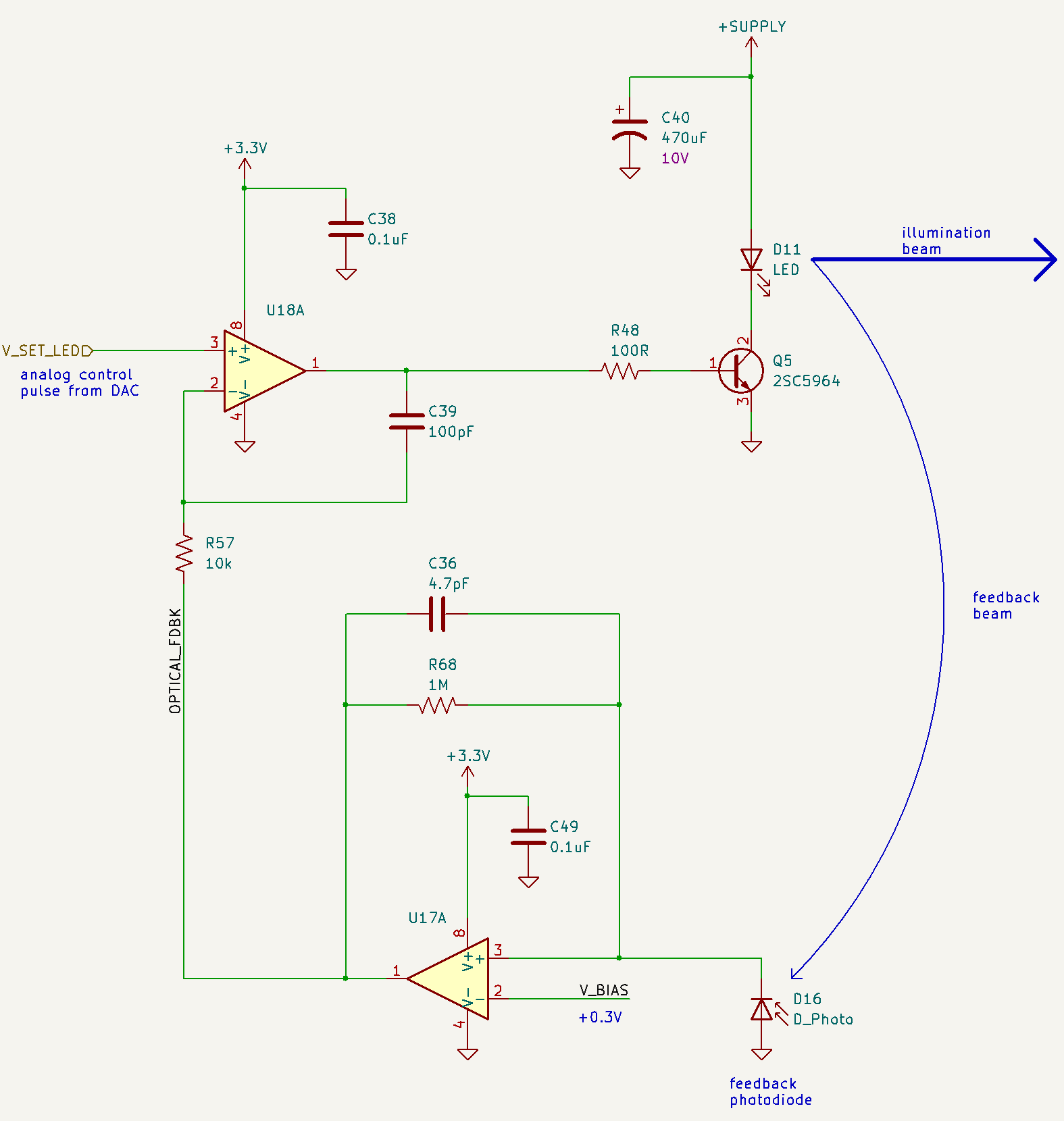
The first topology has one feedback loop (through light).
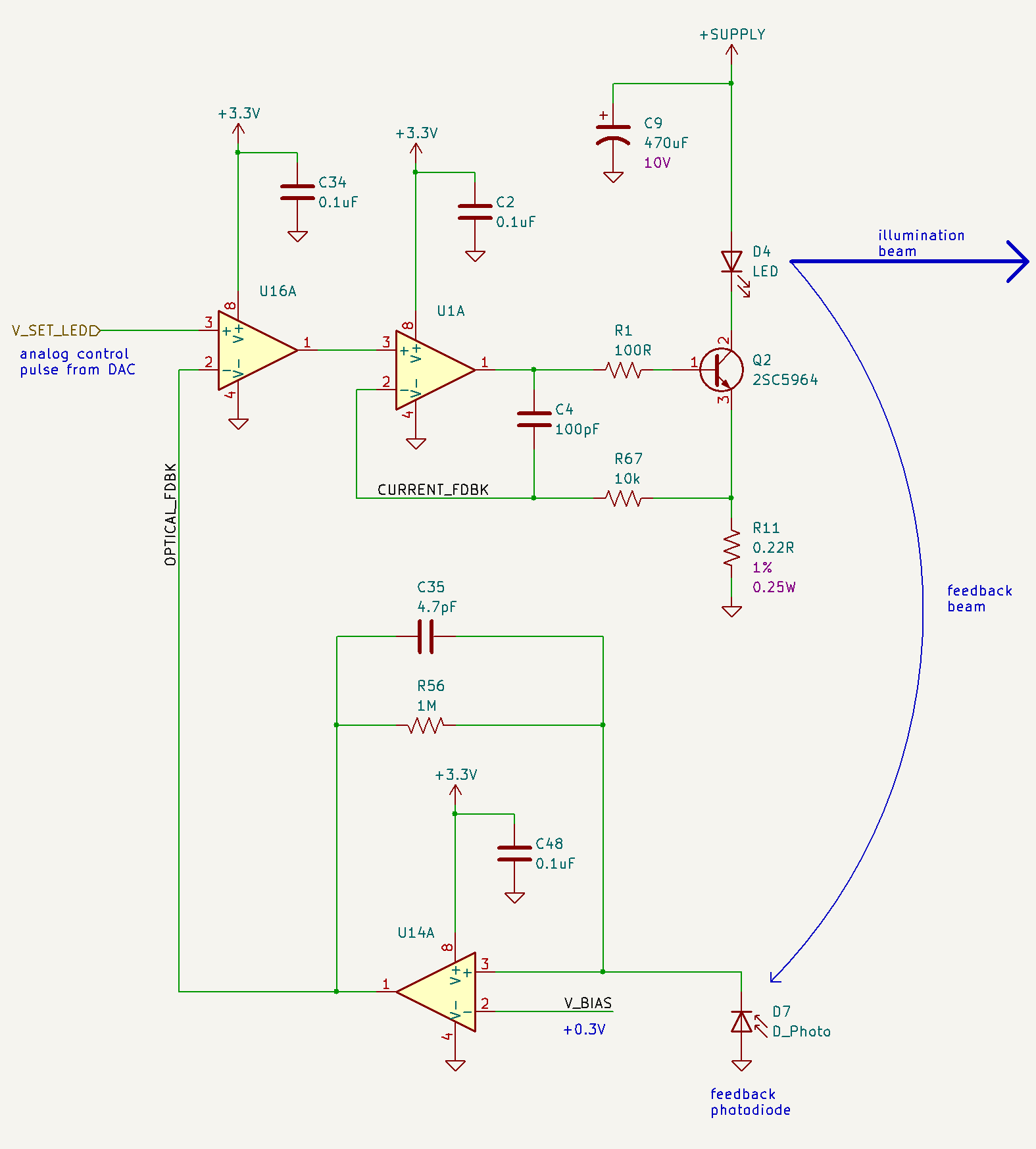
The second topology has two nested feedback loops. The inner look controls constant current through the LED. The outer loop brings in the feedback through light.
Which topology is preferable?
I need to flash the LED with 100us pulses. The present choice of LED is Vishay TSHG6410.
(By the way, I'm interested in other ways of compensating an LED for temperature too.)
1 answer
Which topology is preferable?
The one below because the LED driver is less likely to produce instability and, if it does, you can always tweak C4 (upwards) in order to kill-off the potentially oscillatory pole produced in the response in your first circuit.
How to draw schematics that provide decent visual definition: -
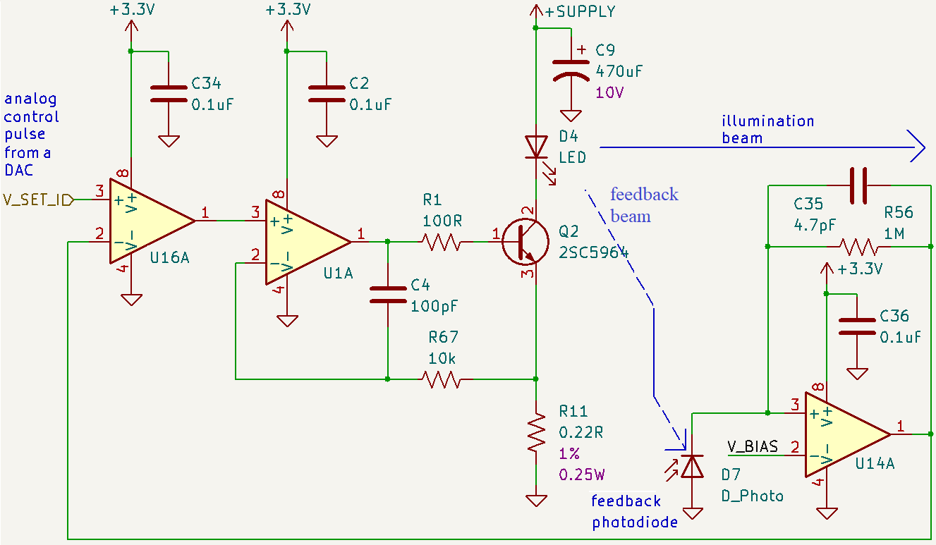
So, concentrate on making an image that can be easily viewed without opening it in a separate tab. You could make it even more readable (than my cut n paste version) with a little care.
0 comment threads

0 comment threads