Comments on Using FET based followers and design rules
Parent
Using FET based followers and design rules
Usually, voltage followers are built with bipolar transistors (or with opamps if better precision is needed). In this case, the simple rule says that the transistor emitter "follows" the input voltage one diode drop below, a somewhat approximate but understandable term.
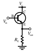
It is perhaps less usual to see field effect based followers, and I'm particularly interested in jfets and mosfets.
From my readings about this topic, it is still unclear to me how to determine the voltage drop introduced by these transistors (parallel to the diode drop for the bipolar transistor follower).
Also, if there is a way to control this drop (without using an opamp), what are the design rules, or perhaps the rules of thumbs ?
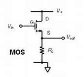
Allow me to address the MOSFET only as a source follower. - this has very unpredictable linear use without voltage …
4y ago
"Also, if there is a way to control this drop (without using an oamp), what are the design rules, or perhaps the rules o …
4y ago
FET source-followers are generally less predictable than BJT (bipolar junction transistor, like NPN or PNP) emitter-foll …
4y ago
> ... it is still unclear to me how to determine the voltage drop introduced by these transistors... Very interesting …
4y ago
In addition to Olin's answer: > and I'm particularly interested in jfets and mosfets. If you decide to go dow …
4y ago
Post
"Also, if there is a way to control this drop (without using an oamp), what are the design rules, or perhaps the rules of thumbs ?"
"I reformulate this question:do you see any reason to use a FET follower?"
(1) As outlined by Olin Lathrop, the voltage drop (that means: The potential difference betwqeen G and S) depends, of course, on the Id=f(Vgs) relation and is less predictable if compared with bipolar transistors. More than that, I think this question concerns the DC voltage properties only.
(2) As far as the second quoted question is concerned, I think we have to consider small signals (if this stage is used as a buffer). And in this respect, the transconductance of the device matters primarily. Look at the gain formula for a CS stage:
A=gmRs/(1+gmRs)= Rs/[(1/gm)+Rs]
As we can see, for Rs>>1/gm the gain approaches unity. Of course, the exactness of the buffer function requires a transconductance as large as possible. And we know that, generally, the BJT can provide a larger transconductance. Hence, as very often in electronics, we have to find a trade-off between exactness of the follower (app. unity gain) and an input resistance (as large as possible).
But the (fixed) DC drop between G and S plays not a major role in many buffer applications.
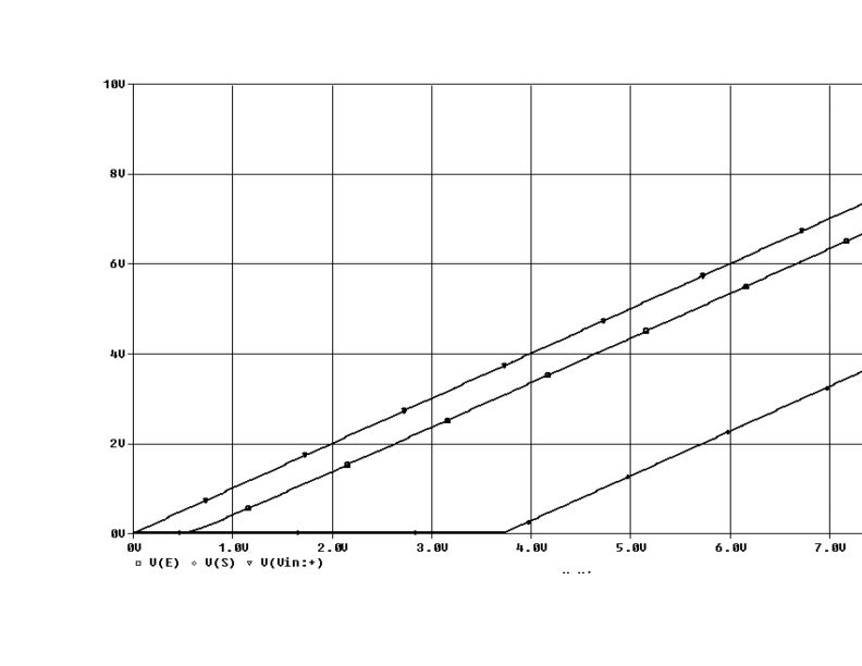
EDIT: In the following SPICE-plot two transistors (BC107 and IRFAC30) are used as an emitter resp. source follower. Supply voltage 9V and a 5k resistor in the emitter resp. source path. The Mosfet type were selected (pos. gate voltage) to enable comparison with the BJT in a common graph.
- Top line: Vin (DC) from 0 to 7 Volts.
- Bottom line: Source voltage (constant offset of app.3.8V)
- Mid line: Emitter voltage (offset app. 0.65V).
As we can see - in both cases: Output follows input with very good linearity (due to heavy feedback)
The jpg file has been added....hopefully

1 comment thread