Comments on Driving LED with NPN transistor from I/O pin
Parent
Driving LED with NPN transistor from I/O pin
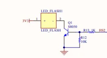
I'm trying to understand a circuit for driving a LED found on a board I purchased.
Below is the circuit driven by an I/O pin (HS2) of a small 3.3V processor.
The HS2 pin is driven by the I/O with these specs:
V(high) = 0.8 · Vsupply = 2.64 V
V(low) = 0.1 · Vsupply = 0.33 V
The I/O pin can be set to drive up to 28 mA, but I am guessing the design of the circuit would rather pull the current from Vsupply rather than the I/O controlling pin (HS2), and that is the reason for using the NPN transistor (S8050) to drive the LED.
The LED is a SMD 3528 white LED for which I do not have specs, but testing shows it lights up nicely at 40 mA, and does fine at 11 mA, with 3.24 V across.
I am wondering if the reason for this design is because this bright white LED is typically looking for a 3 V drop, and if they used a current limiting resistor in series with the LED, then maybe the resistor would drop too much and bring the voltage across the LED to less than 3 V.
How is the 1k/10k voltage divider working to set the current through the flash?
Does this circuit seem like a good one to duplicate if I wanted to create additional LEDs driven by other pins on the processor?
When the transistor is on, is it setting the current, or will the current vary per the gain of the transistor?
I see how this circuit is acting as a switch, but is it also fixing the current through the LED? Or is the current through the LED dependent on the gain of the transistor?
Post
First, let's redraw the circuit a little more clearly, with logical flow left to right. This also protects the answer from possible changes to the question.
As you say, Q1 is a switch to control the LED. Most likely, a separate transistor was used to keep the LED current out of the microcontroller. If the micro was driving the LED directly, the LED current would have to go either thru the micro's Vdd or Vss pins. Those have a fixed current budget, which might have been tight in this design. Using a separate transistor to take the current is a reasonable thing to do.
R1 limits the I/O pin and base currents when the I/O pin is high. At 3.3 V, and assuming 700 mV for the B-E drop of the transistor, 2.6 mA will flow thru R1, most of which goes into the base.
I'm not sure why R2 is there. Maybe there was a reason to make sure Q1 was really off and not picking up stray signals when the micro is powering up and the I/O pin is still in high impedance before the firmware sets it up. Still, this smells more like something done for religious reasons.
The rest of the circuit is a bad idea unless this is a high volume cheap product where reliability doesn't matter much. Something like a toy would fit in this category, for example.
The basic problem is the LED current can vary widely, and even be out of spec. You measured this one sample, and found it to draw 11 mA with 3.24 V across it. The next one could easily draw twice or half that due to part variations alone.
This LED is being voltage-driven, which is bad. Once the diode starts substantially conducting, small changes in the voltage cause large changes in the current. The voltage to get the right current changes with temperature and across parts. Generally there is no single voltage, even if you could accurately guarantee one, that results in high enough current to light well, but not so high as to be out of spec. Note that at high temperature, the C-E drop of the transistor will be lower, and the LED current as a function of voltage will be higher. And, what is the variation of the "3.3 V" supply across units?
The reason for this kind of drive is probably that it was just simpler, and the loss of reliability and repeatability in this design wasn't worth more cost and board space to address.
The easiest way to control the LED more tightly is with a higher supply voltage, like 5 V. That leaves some room for a resistor in series to control the current. That may not have been available, and the reliability wasn't worth the cost.
The HS2 pin is driven by the I/O with specs of V(high) = .8(Vsupply) = 2.64V, and V(low) = .1(Vsupply) = .33V .
You need to look at the datasheet again. First, make sure these are the specs for the output voltages, not the input voltages. Second, these levels are probably at maximum current. Most likely, you are getting much closer to 3.3 V and 0 V in reality. In particular, when the pin is driving low, it must be close to 0 V since it's not sinking any current.
Does this circuit seem like a good one to duplicate if I wanted to create additional LED's driven by other pins on the processor?
Not unless you understand the consequences of possibly running the LED out of spec, and are willing to put up with them.
When the transistor is on, is it setting the current, or will the current vary per the gain of the transistor?
The transistor gain is not limiting the current in this design. You have 2.6 mA base current. Even at 30 mA LED current, that only requires a gain less than 12. I didn't look up your transistor, but cheap small signal transistors can easily be found to guarantee a gain of 30 or more in this case.
The problem is that the LED current will vary across LEDs, over temperature, and with small variations in the supply voltage.


1 comment thread