Comments on Ceramic filter vs ceramic resonator
Parent
Ceramic filter vs ceramic resonator
I have a design of a power line communication using the following IC.
https://www.yamar.com/datasheet/DS-SIG60.pdf
My design is the same as the example circuit in the datasheet of the chip.

The schematic above uses integrated ceramic filters. There are also some suggested part numbers in the datasheet.
However I can't find any in the market.
This is the part I'm looking for: LTSH6.0MDB
But I can find many ceramic resonators and crystal resonators instead.
What is the difference between a ceramic filter and a ceramic resonator?
I have placed a ceramic resonator instead.
This is the part number I placed instead in the position of F0.
Of course I have set up the chip to work at 6MHz (Instead of 5.5MHz which is the default) frequency because that component has center frequency 6MHz.
But still it doesn't seem to work as expected.
I can receive bytes but there's a lot of garbage in the communication.
F1 is optional and I didn't include it in the design.
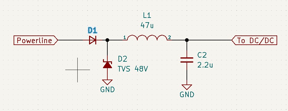
I use it for powerline communication over DC voltage 12V to 36V.
I have also included the proper low-pass DC filtering in its DC/DC power supply in the board. As mentioned in the datasheet.
I think the problem is in the ceramic resonator I put instead of a ceramic filter (that's why the title). However despite that I can see signal comming on the analog parts of the chip, with my oscilloscope. The amplitude of that signal is above 1Vpp, around 2Vpp. Which is way enough for a proper communication according to specs.
Post
The following users marked this post as Works for me:
| User | Comment | Date |
|---|---|---|
| DeadMouse | (no comment) | Oct 18, 2022 at 15:54 |
The Murata part you have chosen as a replacement is unsuitable. Its only application is to cheaply replace crystals in oscillators and, as such, it will have a profoundly tight bandwidth (maybe less than 100 Hz or so) whereas the original filter you linked has a 20 dB bandwidth of 750 kHz (as per the other document you linked).
Also, if you read this data sheet on the original filter you would have liked to use, it says the 3 dB bandwidth is 60 kHz. And, if you read the data sheet for the chip it says this: -$$$$
3.1.2 Ceramic Filter Considerations The SIG60 is designed to operate with one ceramic filter for transmission and reception. However, if switching between two channels is desired, two ceramic filters are required. The minimum allowable bandwidth of the ceramic filters is +/-60 kHz @ 3dB. Narrow bandwidth limits the maximal bit rate.
$$$$
Note the bit about minimum allowable bandwidth being 60 kHz (a lot higher than a ceramic resonator. And, it seems like the last sentence might be the easiest to grasp. If you used a data rate that was very slow, you could get away with a tighter bandwidth filter so, maybe as a test, you can drop your data rate to maybe 100 bits per second and see it it all comes good.
Keep testing using an exclusive transmission connection and only when that shows a good sign of working, try communications over the DC link. The other thing to take away is always dig deep until you have the best data sheets. Neither of the ones you linked were suitable for ascertaining the true bandwidth performance.
1 comment thread

1 comment thread