Comments on Ceramic filter vs ceramic resonator
Parent
Ceramic filter vs ceramic resonator
I have a design of a power line communication using the following IC.
https://www.yamar.com/datasheet/DS-SIG60.pdf
My design is the same as the example circuit in the datasheet of the chip.

The schematic above uses integrated ceramic filters. There are also some suggested part numbers in the datasheet.
However I can't find any in the market.
This is the part I'm looking for: LTSH6.0MDB
But I can find many ceramic resonators and crystal resonators instead.
What is the difference between a ceramic filter and a ceramic resonator?
I have placed a ceramic resonator instead.
This is the part number I placed instead in the position of F0.
Of course I have set up the chip to work at 6MHz (Instead of 5.5MHz which is the default) frequency because that component has center frequency 6MHz.
But still it doesn't seem to work as expected.
I can receive bytes but there's a lot of garbage in the communication.
F1 is optional and I didn't include it in the design.
I use it for powerline communication over DC voltage 12V to 36V.
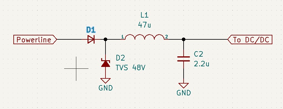
I have also included the proper low-pass DC filtering in its DC/DC power supply in the board. As mentioned in the datasheet.
I think the problem is in the ceramic resonator I put instead of a ceramic filter (that's why the title). However despite that I can see signal comming on the analog parts of the chip, with my oscilloscope. The amplitude of that signal is above 1Vpp, around 2Vpp. Which is way enough for a proper communication according to specs.
Post
The following users marked this post as Works for me:
| User | Comment | Date |
|---|---|---|
| DeadMouse | (no comment) | Oct 18, 2022 at 15:54 |
A resonator cannot replace a filter because the filter has multiple resonances to extend the bandwidth.
For AM carrier modulation using a narrow band resonator with 0.5% tolerance of 6MHz or +/-30 kHz with a Q of 10k and its narrow -3dB BW can be as high as a crystal resonator but > 100 worse tolerance but 10% to 30% the cost of crystal resonators.
I don't know what the 20 dB should be, but the inexpensive ceramic filter is the desired solution if you can find it with the right characteristics.
Discrete filters are hard to make. unless the very high order and using NP0 caps.
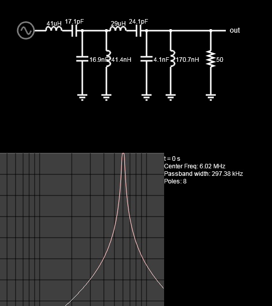
A Ceramic filter is a double-tuned resonator so it has steep skirts but a wider BW. You need about 300 kHz BW or +/-150k unless operating at a lower data rate than max.
The data sheet for this part is seriously lacking any specs for signal quality for signal SNR and filter distortion. It is also obsolete with the newer replacement being the towards a higher frequency range and with 100kHz step bands. Ceramic resonators in this low-frequency range are largely going obsolete also.
1 comment thread

1 comment thread