Communities

Writing
Writing
Codidact Meta
Codidact Meta
The Great Outdoors
The Great Outdoors
Photography & Video
Photography & Video
Scientific Speculation
Cooking
Cooking
Electrical Engineering
Judaism
Judaism
Languages & Linguistics
Software Development
Mathematics
Mathematics
Christianity
Christianity
Code Golf
Code Golf
Music
Music
Physics
Physics
Linux Systems
Linux Systems
Power Users
Power Users
Tabletop RPGs
Tabletop RPGs
Community Proposals
Community Proposals
tag:snake search within a tag
answers:0 unanswered questions
user:xxxx search by author id
score:0.5 posts with 0.5+ score
"snake oil" exact phrase
votes:4 posts with 4+ votes
created:<1w created < 1 week ago
post_type:xxxx type of post
Search help
Notifications
Mark all as read See all your notifications »
Q&A

Comments on What is a good PCB-layout?

Post

What is a good PCB-layout?

+3
−0

I am an electrical engineering student and I just finished designing an ECG-amplifier circuit. Here is the schematic: -

Image alt text

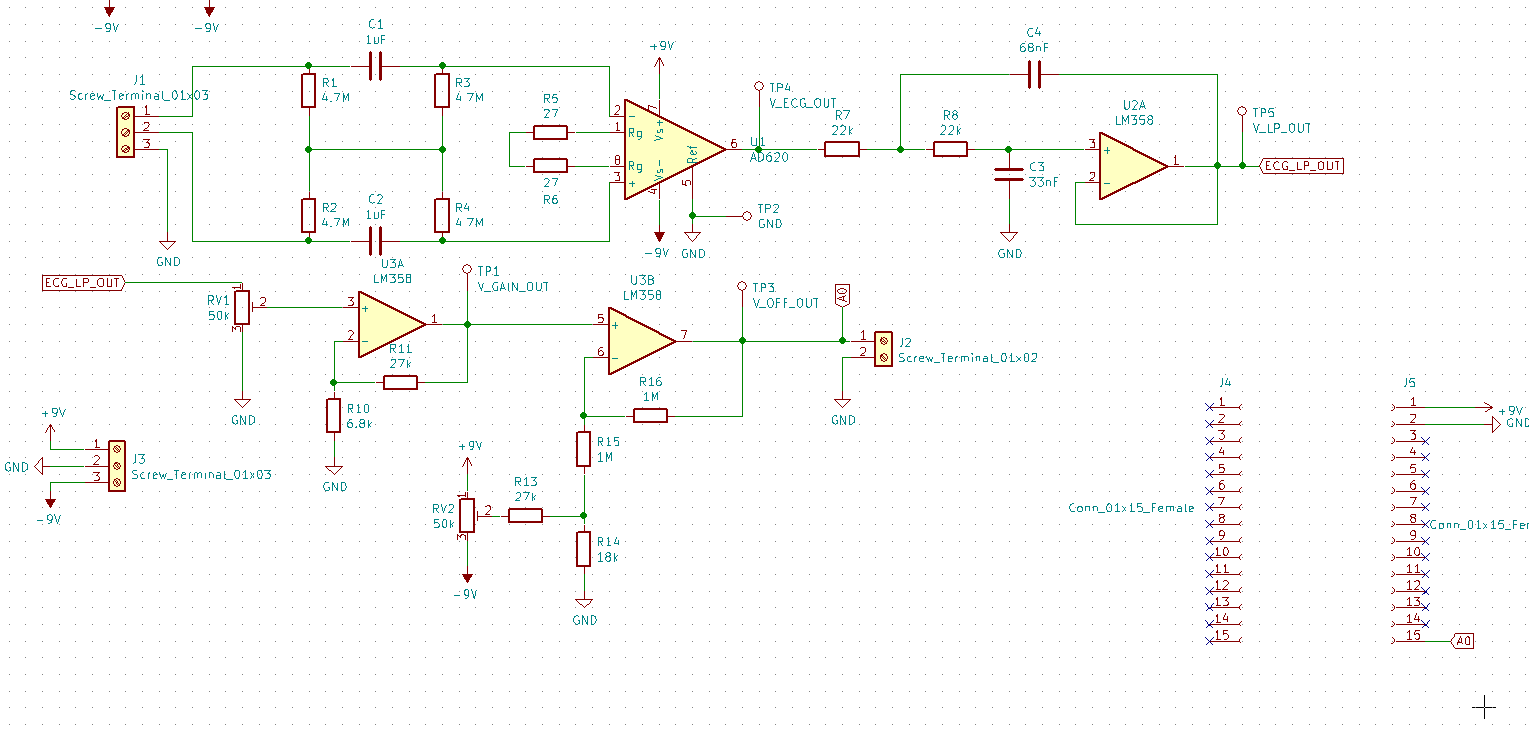
It is fairly simple. Initially, there is a 1st order highpass filter. Then, a differential amplification stage with AD620N in-amp followed by a Sallen-Key 2nd order lowpass filter. Finally, a gain and offset stage. The two female pin-header connectors (J4 and J5) are for plugging in an esp8266 module to sample the processed signal with its ADC. There are also some test points and some screw terminals.

I have also designed and ordered a PCB for this circuit here:

Image alt text

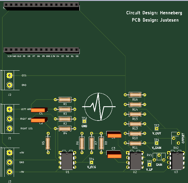
The PCB is 100x100mm, has 2 layers, and it only uses THT-components. The +9V and -9V are connected through traces to the amplifiers, and I use 1 GND plane.

Questions: I'm new to PCB-design and I don't have a feeling for what a "good" design is. Have I made some big "no-nos"? Is there a standard for placing components that's a good idea to follow? Where is it a good place to start with the PCB-design? Should I go from left to right following my schematic and wire components accordingly (that's what I have done)? Is this a poor design?

History
Why does this post require moderator attention?
You might want to add some details to your flag.
Why should this post be closed?

2 comment threads

A good layout is one that meets or exceeds your expectations (or design specs). These specs form wha... (3 comments)
Quite a few questions about the circuit design. Where are the power supply decoupling capacitors for... (5 comments)
Quite a few questions about the circuit design. Where are the power supply decoupling capacitors for...
Nick Alexeev‭ wrote about 1 year ago · edited about 1 year ago

Carl, I have several questions about the circuit design. Where are the power supply decoupling capacitors for the ICs? What's your analysis for patient isolation? This looks like a 3-lead ECG; why are you AC-coupling the Right Arm and the Left arm?

Carl‭ wrote about 1 year ago · edited about 1 year ago

@NickAlexeev I have not used any decoupling capacitors in this design? Is that a mistake? If so, what would they do to my circuit? I don't quite understand what you mean with: What's your analysis for patient isolation. The patient and amplifier are isolated. The amplifier is powered through two 9 V batteries and nothing is connected to building ground or the power lines. The right arm and left arm are AC-coupled to remove the half-cell DC battery associated with the lead electrodes. The highpass filter does also to some degree remove baseline drift caused by movement artifacts - but not that well.

Nick Alexeev‭ wrote about 1 year ago · edited about 1 year ago

(1) Not having decoupling capacitors is an error. (2) The battery powered circuit with wireless communication is an analysis of patient isolation. It sounds reasonable. (3) Only 2-lead ECG is AC-coupled. 3-lead id DC coupled. DC offset is removed from electrolytic effect will be present on both electrodes, so it will be canceled (subtracted) by the InAmp. The residual DC offset is removed downstream of the InAmp DC offset correction loop around the InAmp, or an analog high- or band-pass filter, or a DSP high- or band-pass filter.

Carl‭ wrote about 1 year ago

@NickAlexeev Please post an answer to this question. You have peaked my interest, but writing this in the comment section is not the proper way I feel. Please explain what the addition of decoupling capacitors would do to the circuit.

Lundin‭ wrote about 1 year ago

Carl‭ It's standard practice to always put a 100nF cap close to the supply pin on every IC on the board (unless the IC datasheet comes with specific recommendations). Particularly so on 2 layer boards since you'll have much worse EMC characteristics without a ground plane.