Communities

Writing
Writing
Codidact Meta
Codidact Meta
The Great Outdoors
The Great Outdoors
Photography & Video
Photography & Video
Scientific Speculation
Cooking
Cooking
Electrical Engineering
Judaism
Judaism
Languages & Linguistics
Software Development
Mathematics
Mathematics
Christianity
Christianity
Code Golf
Code Golf
Music
Music
Physics
Physics
Linux Systems
Linux Systems
Power Users
Power Users
Tabletop RPGs
Tabletop RPGs
Community Proposals
Community Proposals
tag:snake search within a tag
answers:0 unanswered questions
user:xxxx search by author id
score:0.5 posts with 0.5+ score
"snake oil" exact phrase
votes:4 posts with 4+ votes
created:<1w created < 1 week ago
post_type:xxxx type of post
Search help
Notifications
Mark all as read See all your notifications »
Q&A

Comments on what should the output be for this use case of the CD4047 chip?

Parent

what should the output be for this use case of the CD4047 chip?

+2
−0

Hello, I am trying to use a CD4047 in monostable, positive-edge trigger mode:

Image alt text

Image alt text

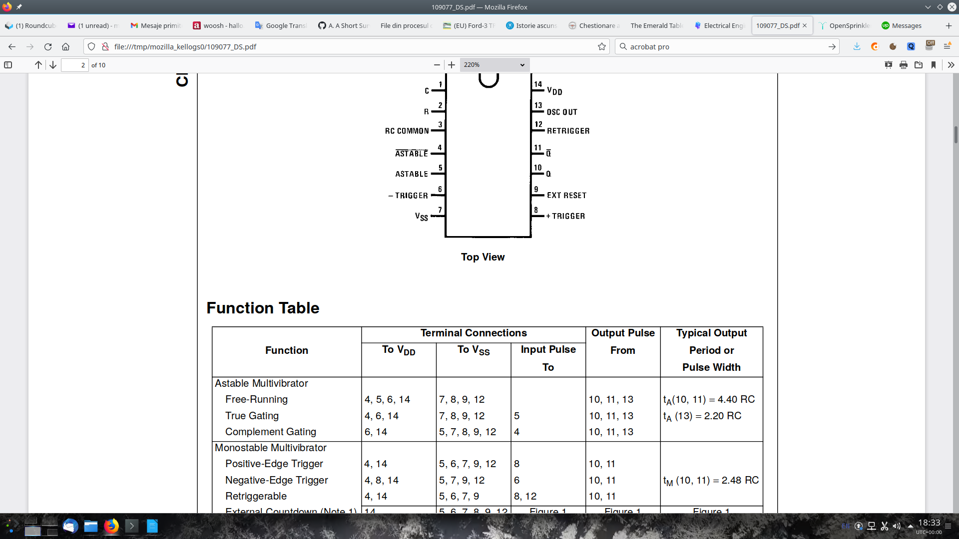
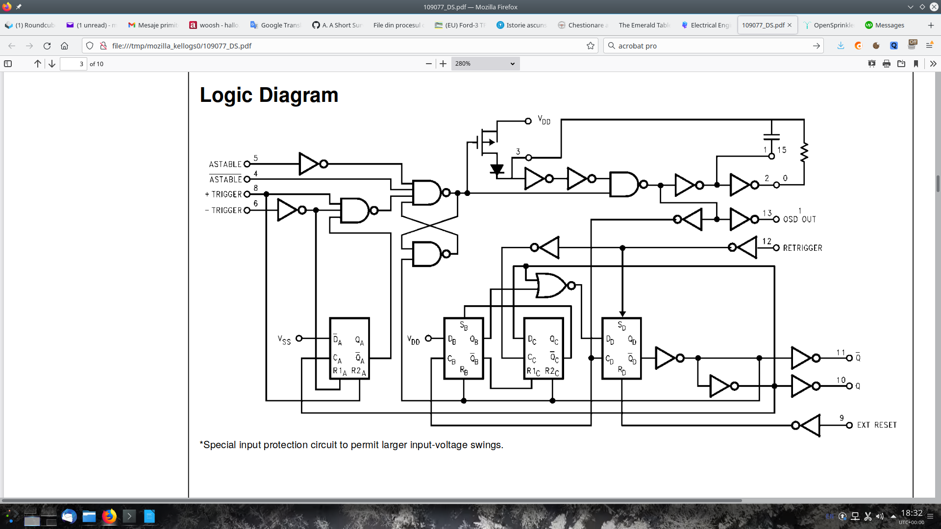
I am not skilled enough to make out what the output, i.e. pin 10, should be when pin 8, the input, is held at 0V (0.1V for some reason). Would expect it to be 0V, I am getting Vdd instead. Is this to be expected? Tried with two chips from different manufacturers bought from different stores.

My diagram:

Image alt text

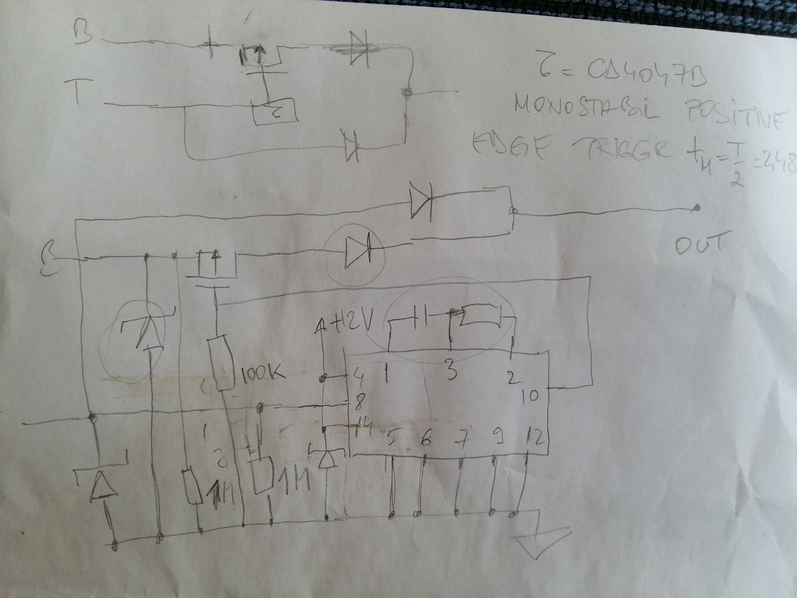
P-MOSFET: FQP17P06 TVS diodes: P6KE18A (Schottky) Diodes: SBCT2040

I am pretty sure everything has been wired correctly; tried on an Arduino UNO @ 5V and car battery @ 12V; I did measure pin 8, input, to be some 0.1 V in the absence of the T signal.


This is getting quite weird. I have been poking at one of the circuit boards doing voltage measurements, putting the B and T signals to 0V / 5V / rectangular 0 -> 5V, it has started working as expected. I have then taken the second board, that one too has started to work as well. Some more fiddling later and only one kept working as expected.

Some hours later and I think both chips are fine. Quitea few cold joints... I am going to retry them both PCBs on the 12V vehicle setup.

History
Why does this post require moderator attention?
You might want to add some details to your flag.
Why should this post be closed?

2 comment threads

Show the schematic (9 comments)
You should be getting 0V (3 comments)
Post
+1
−0

Possibly it is damaged. Be ESD aware and do not power up with any voltage on any pins > 0.5V (Latchup failure)

If raising p9 (reset) does not lower Q to logic "0"=<20% Vdd) replace the IC.

No sweat, be more careful next time for handling failures of ESD etc. Most new IC failures are handling issues or over voltage on power-up which causes excess junction heat from shoot-thru Pch to Nch both ON at the same time.

Image alt text

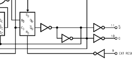
This is the most direct way to test / reset the output.

History
Why does this post require moderator attention?
You might want to add some details to your flag.

2 comment threads

Ensure there are no stored voltages on any pin when power is applied, including avoiding switch bounc... (1 comment)
> Be ESD aware and do not power up with any voltage on any pins > 0.5V (Latchup failure) Not sure ... (1 comment)
> Be ESD aware and do not power up with any voltage on any pins > 0.5V (Latchup failure) Not sure ...
kellogs‭ wrote 10 months ago

Be ESD aware and do not power up with any voltage on any pins > 0.5V (Latchup failure)

Not sure what to make of it. How would one test a circuit without applying power to any pins ?