Comments on Driving LED with NPN transistor from I/O pin
Parent
Driving LED with NPN transistor from I/O pin
I'm trying to understand a circuit for driving a LED found on a board I purchased.
Below is the circuit driven by an I/O pin (HS2) of a small 3.3V processor.
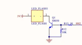
The HS2 pin is driven by the I/O with these specs:
V(high) = 0.8 · Vsupply = 2.64 V
V(low) = 0.1 · Vsupply = 0.33 V
The I/O pin can be set to drive up to 28 mA, but I am guessing the design of the circuit would rather pull the current from Vsupply rather than the I/O controlling pin (HS2), and that is the reason for using the NPN transistor (S8050) to drive the LED.
The LED is a SMD 3528 white LED for which I do not have specs, but testing shows it lights up nicely at 40 mA, and does fine at 11 mA, with 3.24 V across.
I am wondering if the reason for this design is because this bright white LED is typically looking for a 3 V drop, and if they used a current limiting resistor in series with the LED, then maybe the resistor would drop too much and bring the voltage across the LED to less than 3 V.
How is the 1k/10k voltage divider working to set the current through the flash?
Does this circuit seem like a good one to duplicate if I wanted to create additional LEDs driven by other pins on the processor?
When the transistor is on, is it setting the current, or will the current vary per the gain of the transistor?
I see how this circuit is acting as a switch, but is it also fixing the current through the LED? Or is the current through the LED dependent on the gain of the transistor?
Post
No need to power the led with 5V. 3.3 V should suffice!
Before I come to problem of regulating the current with only 3.3V, I wish to state some general simple constructions. Technically speaking, the following current sink/source is perhaps insufficiently known:
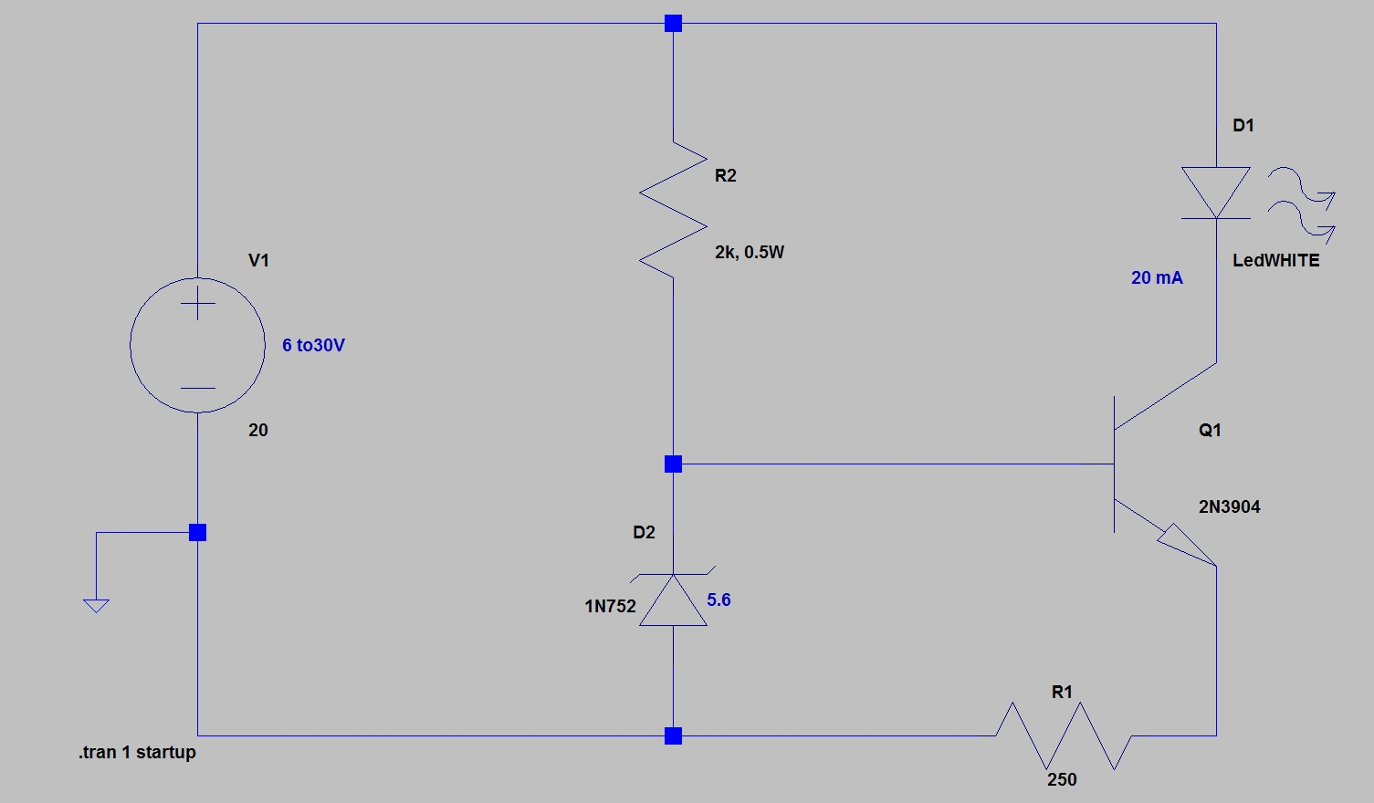
The current is set by I = (V_zener-0.7)/R1. This is a current sink driving a led with 20mA, but with you can obtain a dual circuit with a pnp in place of the npn if you need a current source.
This current sink/source is not only simple, is is also essentially FLOATING; that means that you can replace the ground with a conducting wire in your circuit. This can be especially useful to limit the current from above (I mean not near the ground), even at high voltage (say up to 1000V), and assuming you chose a transistor with suitable rated voltage. Notice also that this circuit can be used as a current source or a current limiter. The fact that this circuit is essentially floating seems not to be well known, as even the Art of Electronics has no other clue than using a high voltage depletion mode mosfet to this purpose.
The above current source has 2 drawbacks: First, it is not very precise, and the current sunk may varies somewhat because of different factors (like temperature etc.). Second, you need a supply voltage at least a bit larger than the zener voltage, and it is difficult to find zener diodes with zener voltage below 3.3V. Nevertheless, the above circuit is still valuable to power LEDs whenever the supply voltage may vary a lot, like in the schematic above where the power supply is allowed to vary from 6 to 30V, for a LED current of 20 mA.
Now, the first drawback above can be easily overcome thanks to the inexpensive TL431 voltage reference:
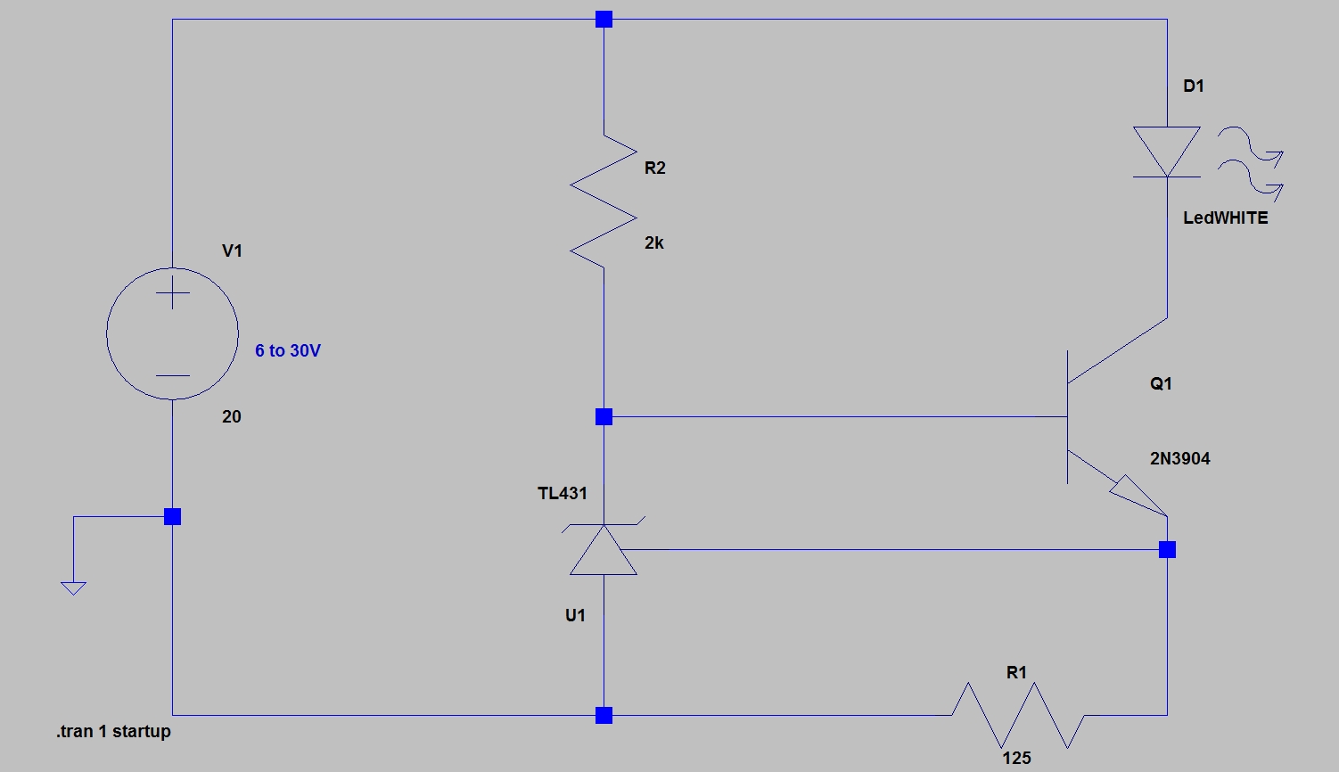
As above, the current limit is set by I = (V_ref-0.6) / R1 = 1.9/R1. Then you have a stable current source that works with a supply voltage from V_ref = 2.5 V to 36V (but the LED needs an additional 3V drop so, this will work from 6V to 36V for a LED). With the component values above, the current sunk is exactly 20mA.
Now let us return to the original problem of the OP of regulating a 3V LED with only 3.3V of supply current. As pointed out by Lorenzo Donati in his comments (acknowledgments), my above solutions cannot work because there is not enough room for the 3V drop of the LED. Olin has pointed out that using a supply of 5V to provide some room is the adequate solution. Nevertheless, just for showing this can be done, I provide below a solution with a 3.3V supply.
The first solution is a current sink with a 2n3904 and an oamp.
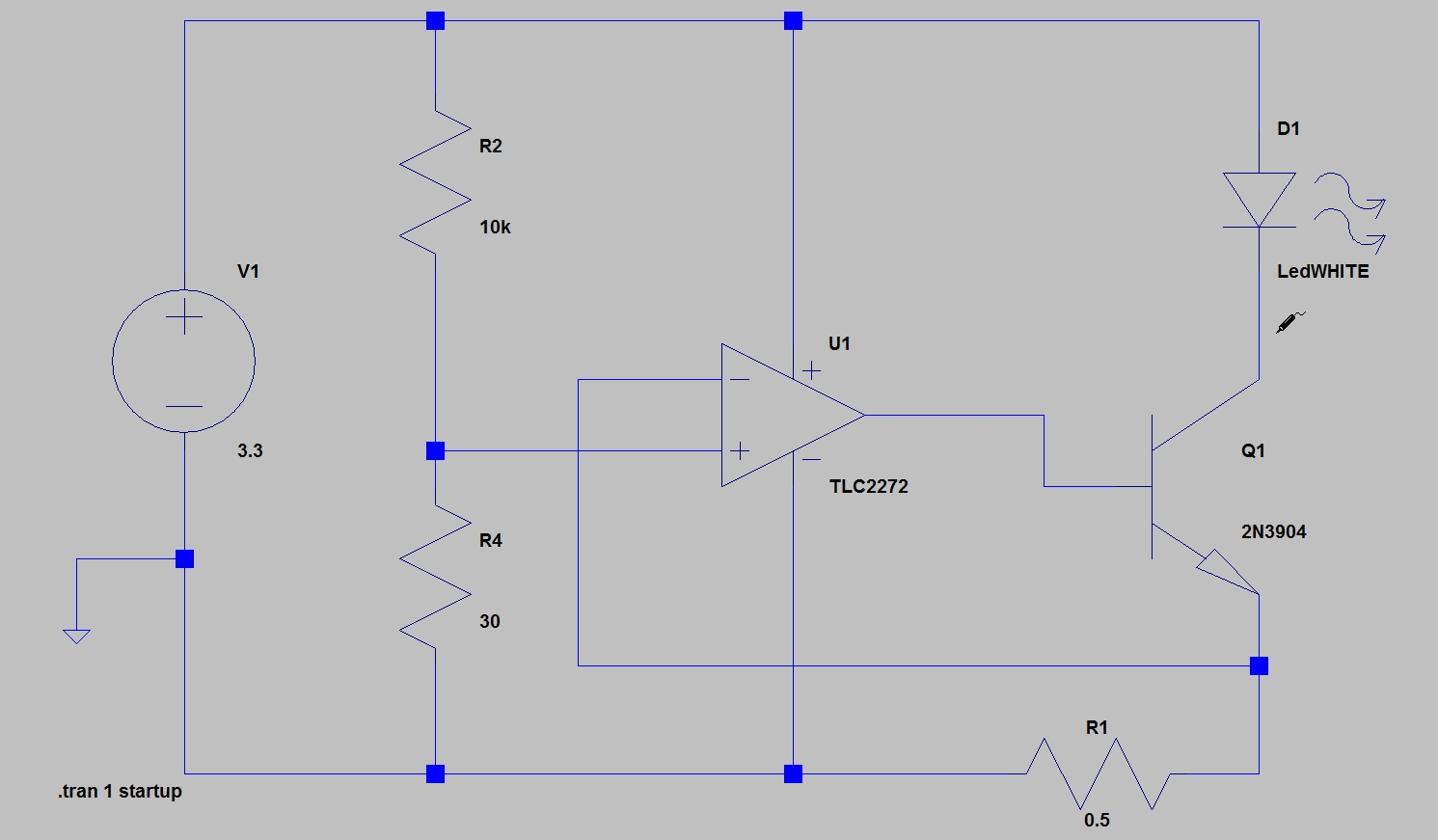
The TLC2272 is one of my favorites, but you can probably do the same with a common LM358.
The current is set with $I_{reg} = V_{in+}/R1$, where $V_{in+}$ is set with the voltage divider, or better, in other circumstances where the supply may vary, with a voltage reference or a Zenner and a voltage divider.
The R1 resistor should be low to reduce as much as possible the voltage drop.
In the above schematic, the current sunk is 17mA according to my simulations, which is probably sufficient in most cases.
This is still not optimal as the npn has a small, but still too high, voltage drop at saturation.
If you want to be really pedant, it is possible to use my favorite IRF7204 MOSFET. It's good to know it: it can switch with only 3V of threshold voltage.
Here is the schematic for a current source driving the LED (pay attention that the input terminals of the oamp have been inverted):
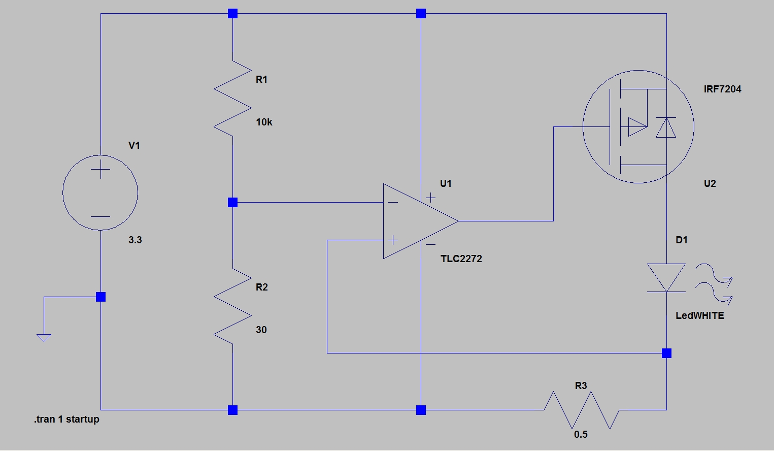
This times, the voltage drop for the LED is almost equal to the supply voltage, which provides even more room for driving a LED at its optimal power.


1 comment thread