Is it possible for one transistor to switch between two loads?
The output collector-emitter part of a transistor can be thought of as a 2-terminal SPST switch controlled by the input base-emitter voltage or base current. So this transistor switch can control only a single collector load.
Is it possible to make the transistor act as a 3-terminal SPDT switch? If so, one transistor will be able to control (switch between) two loads.
In general, can a SPST switch act as a SPDT switch?
3 answers
I suspect this is another of your trick questions and you are waiting for the chance to show us your unrivaled knowledge, but I will play the straight man for you.
No. By definition, an SPST switch can not act as an SPDT switch in general. If that were possible then there would be no need to manufacture SPDT switches, would there?
However, if the trick question really is "Can you use an SPST switch to control two LEDs, so that one goes off and the other goes on when you move the switch, and one of them is always on?" then sure, you can envision a circuit that will do this. But that is not causing a SPST switch to "act as a SPDT switch".
It's not clear what you are really asking, but here is something that might fit your requirements:
First, R1 and R2 can be considered separate loads. The transistor therefore switches two loads.
This circuit can also be used to produce two signals, one inverted from the other. This used to be more common in old tube amplifiers, and was called a "splitter". SIG+ and SIG- would then go off to control the drivers at different ends of the center tapped push-pull output stage, for example.
With bipolar transistors, the currents thru R1 and R2 aren't exactly equal, but can be close enough for many purposes. The discrepancy is 1/gain of the transistor. When this matters, use a Darlington pair, which acts like a single transistor with gain2. Or, nowadays, you'd usually just use a FET.
My idea was to make two non-linear loads (e.g., LEDs with slightly different VF) "help" the SPST switch when switching.
We do engineering here. That includes describing specifications properly so that others can understand them. I've mention before that your descriptions are vague. This needs to be fixed.
I can't even guess what "help the SPST switch when switching" is supposed to mean. SPST switches don't generally need help. If you're talking about a relay, then you either energize the coil or not. No "help", whatever that means, is otherwise required.
A single transistor can certainly drive multiple LEDs with different forward voltages. Just give each their own series resistor to get the current you want thru that LED:
In this example, R2 and R3 can be adjusted so that the current thru each LED is the same, even if they have different forward voltages. For this to work, the V+ voltage must be known and reasonably constant.
My idea was ... the LEDs to act themselves as switches ... consider them together with the transistor as a "composite SPDT switch"
Now it's even less clear what you are asking than before. However, one thing can't be changed, which is that a SPST switch has two output states. No matter how many LEDs you have, there will ultimately be only two different configurations of on/off for the LEDs that you get to select between.
Define what states you want each LED to have for the switch being on and off, and it will be straight forward to design a circuit to achieve that. Put another way, give us a truth table. This must have only two rows, one for switch off and the other for on. It can have as many columns as you like, one for each LED that is to be controlled.
Enough with the hand waving already!
Is it possible for one transistor to switch between two loads?
It seems we finally have a somewhat coherent question. Yes, a single SPST switch can switch between loads. Here is an example where one or the other LED is always lit, depending on the state of a SPST switch:
In this example, the forward voltage of the LEDs is 2.1 V with 10 mA thru them.
When the switch is open, current flows thru R1 and D2. Since D2 drops 2.1 V, the voltage across R1 is (3.3 V - 2.1 V) = 1.2 V. The current thru R1 is therefore 10 mA. This current flows thru D2, so D2 is lit. The voltage across D1 and R2 is only 1.2 V, which is insufficient to get any meaningful current thru D1, so D1 is unlit.
When the switch is closed, D2 has 0 V across it, so is off. The bottom end of D1 will be at ground, so its top end will be at 2.1 V. Using the same math as above, that means 10 mA flows thru R2, which also flows thru D1, so D1 is lit.
Therefore, D2 is on and D1 off when the switch is open, and the opposite when the switch is closed.
However, there is a drawback to this scheme, which is the wasted current thru R1 when the switch is closed. Since the full supply voltage will be applied to R1 in that case, the current thru it will be (3.3 V)/(120 Ω) = 27.5 mA, which dissipates 91 mW as heat.
When, two months ago, I accidentally found out about the new Codidact platform, I was happy and decided to take part in it. I wanted to mark this event with an interesting question that would arouse the interest of visitors to the new platform. Thus I remembered an interesting inventive idea from the distant past that then brought me a patent. And I decided to ask a question about it.
I had two possibilities - to show my possible answer or to wait for others to show their solutions... and I chose the latter. During these two months, my answer matured and I am now sharing it with you.
To best reveal my idea, I will present it in the form of an inventive scenario of 4 steps.
In the beginning, imagine we have two LEDs - red (with VF = 1.5 V) and green (VF = 2.5 V), and we want to switch them so that when one is on the other is off and vice versa.
1. One SPDT controls two LEDs. The most obvious solution is to switch the two LEDs with one SPDT switch - Fig. 1.

Fig. 1. One SPDT controls two LEDs.
Depending on the switch position, the current is steered between the two LEDs. The voltage drop across them varies between 1.5 V and 2.5 V when we switch them... but so far this does not impress us.
The problem is that we can not implement an SPDT switch by one BJ transistor since its collector-emitter part acts as a simple 2-terminal SPST switch.
2. Two SPST control the LEDs. But we can assemble an SPDT switch by two SPST switches - Fig. 2, and they can be implemented by transistors.We have to control them so that when one switch is on the other is off and vice versa. Thus there are two valid combinations.
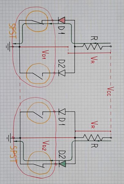
Fig. 2. Two SPST control the LEDs
3. "Invalid" switch combinations (both off or on). But with this implementation, two more combinations are possible, in which we may inadvertently fall. First, both switches can be off. Second, which is more interesting, is the combination when both switches are on - Fig. 3.
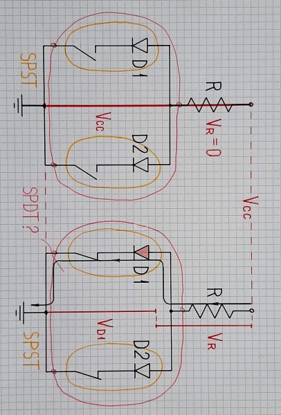
Fig. 3. "Invalid" switch combinations (both off or on)
We expect both LEDs to light up, but to our surprise only the red one lights up. Why? The threshold voltage of the red LED is lower than that of the green one. Therefore, when connected in parallel, the current is steered to the red LED. Can not we use this phenomenon to simplify the circuit?
4. One SPST controls the LEDs. Obviously, the right switch is redundant. It does nothing because the LEDs switch themselves. Then let's remove it - Fig. 4. Now the left switch turns on the red LED that, in its turn, turns off the green LED.
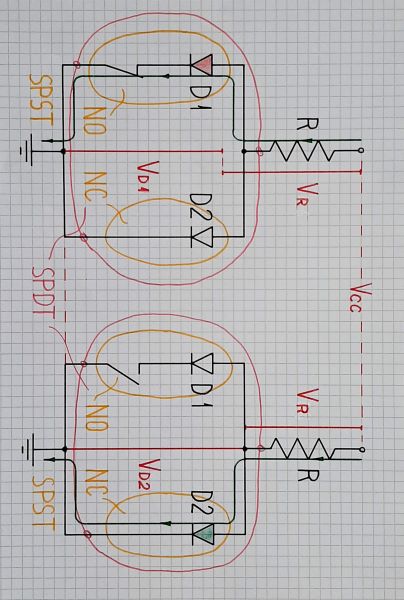
Fig. 4. One SPST controls the two LEDs
5. Application. I have implemented this idea in the circuit of a 3-LED voltage indicator where two transistors control three LEDs. A fragment of this circuit is shown in Fig. 5 in the case the input voltage VIN is positive.
Initially, the input voltage is zero and the transistor T1 is off. The current flows through the green LED D1 and it is lit. If the voltage becomes positive, T1 turns on and connects the red LED D3 in parallel to the green D1. As a result, D1 goes out and D3 lights up.
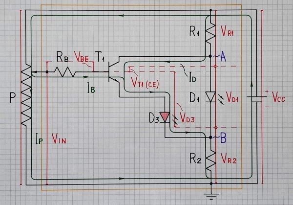
Fig. 5. The idea is implemented in the circuit of a 3-LED voltage indicator (at positive input voltage).
When the input voltage VIN becomes negative, T2 turns on and connects the red LED D2 in parallel to the green D1. Now, D1 goes out and D2 lights up.
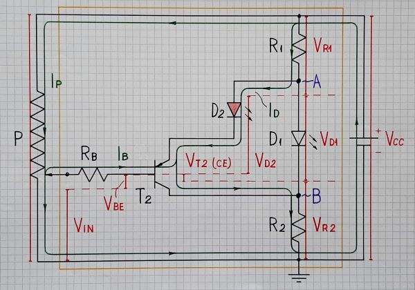
Fig. 6. The 3-LED voltage indicator at negative input voltage.

0 comment threads