Why Ib=const. for BJT output characteristics Ic=f(Vce)
Introduction: In some books and other technical papers (also from universities) it is - surprisingly - still claimed that the bipolar transistor (BJT) would be a current-controlled element. This is simply stated - without any explanation or proof (which I think is impossible).
But of course, the other representation (voltage-controlled) can also be found in many knowledge sources - just as it is considered in the SPICE models.
For me and also for many students this is an unsatisfactory situation. Therefore, I consider the distinction (current vs. voltage-control) to be very important to avoid contradictions between theory and practice. Because many circuits and observable effects can only be explained with voltage control Ic=f(Vbe).
As one argument pro current control often the output characteristic Ic=f(Vce) is referred to, where the base current Ib is considered as a fixed parameter (Ib=const). And - as a matter of fact: Although the collector current Ic is determined by the voltage Vbe, the characteristic curves Ic=f(Vce) are practically always given only for different (fixed) base currents Ib.
My Question: Why ?
EDIT: In response to Elliot Alderson`s comment I enclose a short contribution from the great Barrie Gilbert.
4 answers
You are accessing this answer with a direct link, so it's being shown above all other answers regardless of its score. You can return to the normal view.
Getting into wars about whether something is current controlled or voltage controlled is pointless. In most cases, there is some of both going on. Which "one" to call it then has more to do with personal biases than physics.
However, the real answer is that we do electrical engineering here. Models of how a bipolar transistor work in our context are for helping us understand transistors for the purpose of using them in circuits. The underlying physics may provide insights, but in the end, it is ultimately irrelevant.
All explanations that go into details of holes, electrons, depletion regions, carrier diffusion, and the like, miss the point. What we are interested in is what a transistor does largely as a black box.
For designing circuits, the first model of a BJT is
A little B-E current allows a lot of C-E current.
Followed closely by
B-E looks like a diode.
which also means that
The B-E voltage is about one diode drop during normal "on" operation.
and there is also
The C-E voltage is about 200 mV in saturation, more when the current is "high".
I've been designing circuits professionally for decades, and I can tell you that the above four simple guidelines get you quite a long way. That's usually good enough for conceiving of the overall circuit topology. Once you get into details, you make sure to select a transistor that can withstand your maximum voltage, maximum collector current, power dissipation, make sure the gain is enough, etc. I'm not trying to minimize those, but they are details in the overall scheme of designing circuits.
Even when you do look under the hood, it is still quite reasonable to think of BJTs as current-driven. You try to move charges from the emitter to the base (create a base current). However, most of those charges that get into the base region get swept to the collector before they can come out the base lead. Those "charges swept to the collector" are a current. What this says is that to get a certain base current, you end up with lots more collector current (when the device is properly biased).
If you want to think of a BJT as voltage-controlled, that's fine. You can argue the physics both ways, since its not black and white. However, for the purpose of circuit design, the current-controlled model of a BJT is a lot more useful in my experience.
Question: Are there further arguments for publishing the output characteristics for Ib=const. and not for Vbe=const.
In most circuits, Ib is what we are varying. That's the signal. Vbe comes along for the ride, and usually doesn't vary much, and the variations aren't usually relevant.
Current is always the result of a voltage, not vice versa. We need an E-field to enable movement of charges (which we call "current"). Am I wrong?
Yes, and pointless. This is just the high tech version of the chicken versus egg argument.
An E-field causes a force on charges, but it takes displaced charges to cause an E-field. You can keep going round and round about which comes first, but it's all pointless. It doesn't help in designing circuits nor in understanding the physics.
There are also other ways to move charges than due to an E-field, like a changing magnetic field or physically moving charged objects. Transformers and the alternator in your car work on the first principle, and Van De Graaff and Kelvin generators on the second. Moving charged objects is also apparently how the large E-fields that cause lightning arise.
Again though, this is all pointless bickering that distracts from understanding the underlying physics, and how to use it to design circuits.
In some books and other technical papers (also from universities) it is - surprisingly - still claimed that the bipolar transistor (BJT) would be a current-controlled element.
And this is true, subjected to some conditions and approximations.
This is simply stated - without any explanation or proof (which I think is impossible).
On the contrary, this is very possible and follows from an approximation of the Ebers-moll model.
For me and also for many students this is an unsatisfactory situation. Therefore, I consider the distinction (current vs. voltage-control) to be very important to avoid contradictions between theory and practice. Because many circuits and observable effects can only be explained with voltage control Ic=f(Vbe).
Current control is by far the most useful and intuitive representation, that allows to quickly arrive to the understanding of most common circuit topology (e.g. follower). Sure, this model fails to explain everything and fails to be sufficiently precise in some situations. This is where you need the Ebers-Moll equations and the Early effect.
But this design procedure cannot be used as a proof for a control of the collector current by the base current.
Indeed. For a proof, see theoretical expositions, or even Wikipedia, at Bipolar junction transistor, section "Ebers–Moll model".
Interesting thoughts... BTW where can we see the "current control" in the circuit of a follower?
Let me oversimplify things, by assuming the beta of the transistor is 100, which is a relatively frequent value. So, being current controlled means:
Only 1 percent of the emitter current comes from the base, and 99% of the emitter current comes from the collector.
If the beta is not 100, you use 100/beta percents in place of 1 percent. But thinking with beta = 100 is excellent for the intuition.
This being said, consider the follower topology:
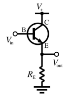
We know, of course, that the emitter voltage Vout is one diode drop below the base voltage. This does not mean, still, that the emitter voltage "follows" the original signal coming to the base, because the signal in Vin has an output impedance (that is usually high). If the base of the transistor loads too much Vin, then the voltage at the base is lower than the original signal, exactly like if you load too much a 1.5V battery with a 0.1 Ohm resistor (say), then the output voltage is less than 1.5V.
This is where our rule above comes into play: since the emitter current sinks only 1% of the base current, it is immediately apparent that the signal is loaded 100 times less than if it were loaded directly without the transistor. This is the real point of the follower circuit.
So, in order for the emitter voltage to follow the signal (one diode drop below), it suffices to make sure the signal can provide 1% of the current sunk by the load, without being degraded.
Another way to say that is that we want the output impedance of the signal be at most 100 times greater than the load impedance of the transistor. This is often abbreviated as:
Be sure the base signal is sufficiently stiff with respect to the maximal emitter current of the transistor.
If this is not the case, and it is impossible to decrease the output impedance of the signal, just use a transistor with a beta > 100. For example, the beta of a Darlington is often 1000 or larger.
show me one single proof that Ib would determine/control Ic
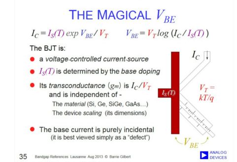
OK. Here is one: From Wikipedia (see link above), The unapproximated Ebers-Moll equations used to describe the three currents in any operating region are given below. These equations are based on the transport model for a bipolar junction transistor $$ i_{\text{C}} = I_\text{S} \left[ \left(e^\frac{V_\text{BE}}{V_\text{T}} - e^\frac{V_\text{BC}}{V_\text{T}}\right) - \frac{1}{\beta_\text{R}} \left(e^\frac{V_\text{BC}}{V_\text{T}} - 1\right) \right] $$
$$i_{\text{B}} = I_\text{S} \left[ \frac{1}{\beta_\text{F}} \left(e^\frac{V_\text{BE}}{V_\text{T}} - 1 \right) + \frac{1}{\beta_\text{R}} \left(e^\frac{V_\text{BC}}{V_\text{T}} - 1\right) \right] $$
$$ i_{\text{E}} = I_\text{S} \left[ \left(e^\frac{V_\text{BE}}{V_\text{T}} - e^\frac{V_\text{BC}}{V_\text{T}}\right) + \frac{1}{\beta_\text{F}} \left(e^\frac{V_\text{BE}}{V_\text{T}} - 1\right) \right] $$
Now, I only consider "normal mode" of operation, that is Vc > Vb > Ve.
So, Vbc < 0. That means that we can neglect all the terms $$e^\frac{V_\text{BC}}{V_\text{T}}$$ in the equations.
Now, Vbe is at least 0.5V for silicone transistors, and Vt is 26mV at room temperature. Hence Vbe/Vt = 19 at least. That means than in the expression of Ib, the huge term exp(Vbe/vt) dominates all the other terms, and we have approximately $$I_B = I_S \frac{1}{\beta_F} e^\frac{V_{BE}}{V_T}.$$ Similarly, we have approximately $$I_E = I_S \left(e^\frac{V_{BE}}{V_T} + \frac{1}{\beta_F} e^\frac{V_{BE}}{V_T}\right).$$ According to Wikipedia again, beta_f is at least equal to 20, so, we can neglect the second term inside the parentheses in the above expression. We get finally $$ \frac{I_E}{I_B} = \beta_F,$$ as desired.
I am polite and do not comment on etc.
Well, yesterday, I felt at some stage like you refuse to admit simple truths and proofs, and simply like useless discussions. Waking up this morning, I thought there may, after all, be some additional point to clarify. I update for the last time this answer, then you'll decide if you still want to be only "polite".
To sum up, you cannot admit (intuitively) that we get rid the exponential form of the "voltage controlled" model, to end up with a simple proportion rule between base and emitter currents.
Well, the truth is that the exponential "voltage controlled" form has never gone (even at the elementary and approximate level); On the contrary, it is always present and used by EE !
Let me elaborate: we have seen above that, under some wide conditions, and in the normal operation mode, the Ebers-Moll equations are approximately
$$I_B = I_S \frac{1}{\beta_F} e^\frac{V_{BE}}{V_T}, $$ $$I_C = I_S \ e^\frac{V_{BE}}{V_T}.$$
This is a system of two equations. Dividing the second equation by the first, we get, as above $$ I_C = \beta_F I_B. \ \ \ \ \ \ (*)$$
But that is a single equation; in the original system, there are two equations, and two equations cannot be equivalent to a single equation. So we need another equation to complete equation (*). We can pick the second equation in the original system. What does it mean? it means basically that Vbe is equal to one diode drop!!! (I drop the mathematical proof). So, finally, the original system is equivalent to the following system: $$ I_C = \beta_F I_B,$$ $$ V_{BE}\ \text{is equal to one diode drop}.$$
As you see, the "voltage controlled" form has never gone, since the diode drop property is one of the two most basic rules always used together with current control; but IN A FIRST APPROXIMATION, it adopts the trivial form of "diode drop". On the other hand, the "current control" equation is not trivial, although simple. This is why it is usually said the transistor is a current controlled device.
TO SUM UP: two equations are needed to describe the transistor behavior. The approximate Ebers-Moll are two "voltage controlled" equations, while the "current model" is one "current controlled equation" and one "voltage controlled equation". The two approximate models are equivalent. But the ultra simple form of the current model system explains why it is so widely used.
My Answer:
There are only practical reasons for a representation with Ib=const. These characteristics are primarily used to determine the DC working point (Ic_o, Vce_o) - together with the working line (resistors Rc and Re).
Would it be helpful and useful to be able to read the corresponding voltage value Vbe_o? No - because due to the input characteristic curve (e-function) the curves for the most interesting values (0.65 V...0.7 V ) are very close together (and are subject to very large tolerances).
It is, therefore, common practice to use instead a standard value (0.7 Volt) for dimensioning, the exact value of which does not have a great influence on the collector current if the Re-stabilization is good. Furthermore, to calculate the base supply circuitry, the corresponding base current Ib_o must be found anyway. Therefore, for practical reasons, it makes sense to use from the very beginning the characteristics Ic=f(Vce) where the base current can be found immediately (parameter Ib=const).
But this design procedure cannot be used as a proof for a control of the collector current by the base current.
Question: Are there further arguments for publishing the output characteristics for Ib=const. and not for Vbe=const.
EDIT (response to coquelicot):
Perhaps you misunderstood my position.... certainly my fault.
I never have denied that Ib does exist. And I never have denied that there is a MODEL for current control. And this model works in some cases - however, there are many circuits (e.g. current mirror, RE-feedback...) and effects (tempco -2mV/K, EARLY effect,..) which cannot be explained with this model (because it does not reflect the physical reality).
I have many more examples: Try to explain the common-base stage or the cascode principle or the function od the long-tailed pair with the current-control feature.... Here, we need the transconductance model with gm=d(Ic)/d(Vbe)=Ic/VT.
This reality is given by the Ebers-Moll equations. It is quite simple: The emitter current is given by an exponential function Ie=f(Vbe) which then is split into two (exponential) currents Ic=f(Vbe) and Ib=f(Vbe). These three currents represent a cause-and-effect-relation. I am sure that you will agree up to this point.
Now comes the step which I consider as wrong:
Of course, we can divide the two equations for Ic and Ib (as you did) - and we get a relation between Ic and Ib - but this relation is a CORRELATION and must not be interpreted as a control function (Cause-and-effect in a physical sense). Of course, from the mathematical point of view, everything is correct. But the causality is lost because the voltage Vbe is the cause for BOTH currents. Do you think that 2 charged carriers injected into the base could release 500 carriers from the emitter (assuming B=250)?
Simple example: Voltage source V1 drives curents through two parallel resistors R1 (current I1) and R2 (current I2). From the current divider rule we get: I2=I1*(R1/R2).
From this relation, would you derive that the current I2 is "controlled/determined" by I1 ?
PS: It was not my intention to discuss again the question voltage vs. current control (this was discussed elsewhere several times). But your response gave me no other choice. The core of my contribution was only the question why the BJT output characteristics are given (in most books and data sheets) for Ib=const. and not for Vbe=const.. I have tried to find a possible answer and I am waiting for some comments to my answer.
I fully agree with OP considerations about measuring the transistor output curve. We can very easily and precisely set successive current values with constant increment. Thus, the IV curves will be evenly spaced vertically (equidistant from each other).
Let me generalize these observations into a "golden rule":
Golden rule 1: If you want to set precisely the voltage across and current through a voltage-stable non-linear element (diode, base-emitter junction of a transistor), drive it by a current source. Otherwise (if you control it with a voltage source), the current will change rapidly and it will be difficult to set the operating point. It is interesting that, in other applications (such as a differential pair), this effect (aka "current steering") is useful.
We can formulate another but dual "golden rule":
Golden rule 2: If you want to set precisely the voltage across and current through a current-stable non-linear element (collector-emitter junction of a transistor), drive it by a voltage source. Otherwise (if you control it with a current source), the voltage will change rapidly and it will be difficult to set the operating point. As above, there are applications (e.g., the so-called "dynamic load") where this effect is useful.
Finally, we can combine them into a more general "golden rule":
Golden rule 3: If you want to set precisely the voltage across and current through a non-linear element, drive it by the opposite kind of source.
Are there further arguments for publishing the output characteristics for Ib=const and not for Vbe=const.
Maybe the Earley effect? Or the temperature dependence?
I remembered that I asked such a question in RG network a few years ago - Why do we use Ib instead Vbe as a parameter when measuring common-emitter output characteristics?
Maybe the discussion there can help...

1 comment thread