PWM Triangle Wave from two clocks
What follows is a proposed concept of a simple (in principle!) way to generate a fixed-amplitude triangle wave, using two clocks, an XOR gate, and not using any processor cycles.
It is practical in the low-mid-100-Hz ballpark, with typical mcu clocks. Motivating application is dither waveform for solenoid valve control signals.
SUMMARY
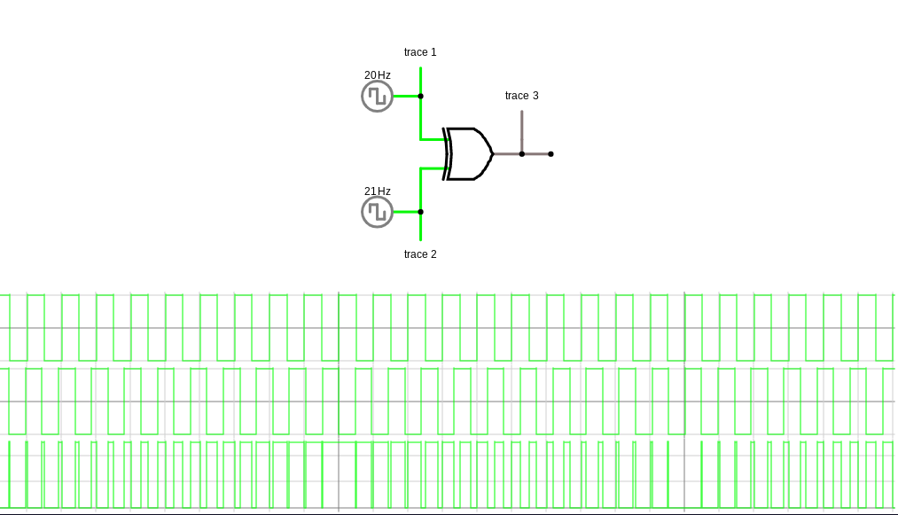
Two timers output two clocks A, B, with fixed 50% duty cycle. XOR(A,B) produces a symmetrical PWM triangle wave, with modulation frequency at ($f_{\rm A} + f_{\rm B})$ , and triangle frequency at $(f_{\rm A} - f_{\rm B})$. No other additional hardware. Illustrated below, showing how the XOR output is equivalent to a PWM. (click to zoom)
Given a master clock $f_{\rm CPU}$, the available frequencies are:
$$f_{\rm TRIANGLE} = \frac{2 f_{\rm CPU}}{(n^2 - 1)}$$
"$n$" should be an odd integer. The two clocks are set to $f_{\rm CPU}/(n+1)$ and $f_{\rm CPU}/(n-1)$, to make the dividers even numbers, so that A and B can have 50% duty cycles.
The low-pass filter design is also parametrized by $n$. Let's define the passband at the triangle’s 5th harmonic, and the stopband at $(f_{\rm A} + f_{\rm B})$. The dimensionless value $f_{\rm STOP} / f_{\rm PASS}$ will represent the filter's transition band, and this value comes out to $n/5$.
The dimensionless transition band corresponds to "filter complexity". A narrower transition band places more demands on the filter design. Given a lower limit of this value, a practical upper limit for the triangle frequency can then be derived as
$$ \frac{f_{\rm TRIANGLE(max)}}{f_{\rm CPU}} = \frac{2}{25} \left(\frac{f_{\rm PASS}}{f_{\rm STOP}}\right)^2$$
The table below uses this formula to show typical limits of the application:
| min acceptable $f_{\rm STOP}/f_{\rm PASS}$ | max $f_{\rm TRIANGLE}/f_{\rm CPU}$ |
|---|---|
| 20 | 1 / 5000 |
| 40 | 1 / 20000 |
| 60 (shown in example) | 1 / 45000 |
| 80 | 1 / 80000 |
| 100 | 1 / 125000 |
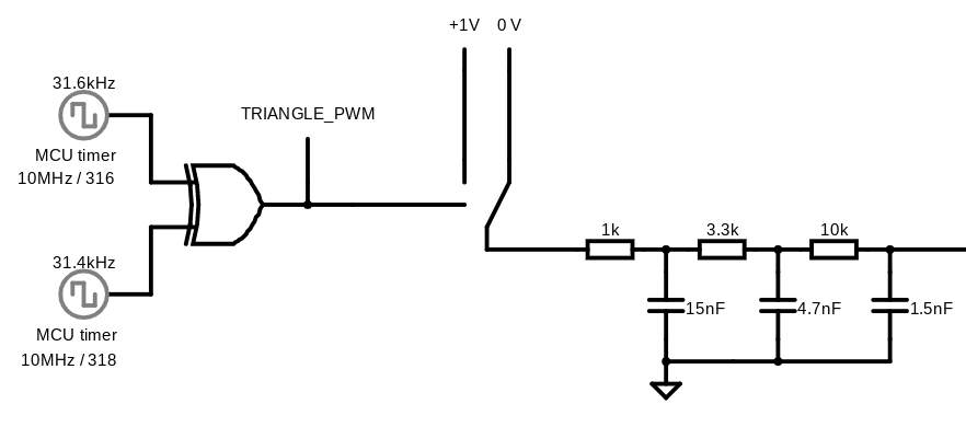
Example Circuit producing 199Hz from 10MHz f_cpu
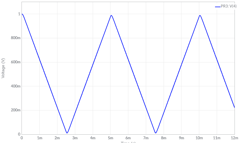
Simulation of above circuit. 0-1V inputs produce 12mV - 988 mV peaks
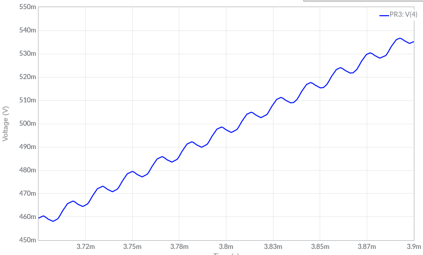
Detail showing less than 1% ripple.
Additional details of the analysis, and example showing the design calculation, are here (pdf file, 5 pages).


1 comment thread