Current and voltage of inductor
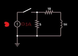
How do I find the current through the inductor and the voltage of the inductor after the switch is closed?
2 answers
You are accessing this answer with a direct link, so it's being shown above all other answers regardless of its score. You can return to the normal view.
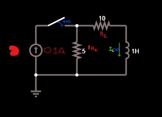
For reference, here is your circuit properly drawn with component designators:
The question is what happens when the inductor current starts at 0, then the switch is closed.
The first observation should be that the current source and the two resistors can be reduced to the equivalent Norton or Thevenin circuits. That is a current source with a single resistor in parallel, or a voltage source with a single resistor in series. The two are equivalent from the inductor's point of view. I'll pick the Thevenin version:
The current function should now be obvious from inspection because it's a simple L-R decay:
I = Ifinal⋅(1 - e-t/Τ)
I = (V1/R3)⋅(1 - e-t(R3/L1))
We can easily see that:
- The initial current is 0.
- The "final" current is V1/R3 = (5 V)/(15 Ω) = 333 mA.
- The time constant is L1/R3 = (1 H)/(15 Ω) = 66.7 ms.
the time costant is L1/R so the t/T must have units of Ohms*seconds/Henries
I'm not sure what you are getting at. Resistance divided by inductance yields units of time. Specifically, Henrys / Ohms = seconds.
Ah, I just noticed that I accidentally flipped the time constant in the equation above. The exponential is supposed to be e-t/Τ, with Τ being L1/R3. I'll go fix that now.
2 comment threads
After the switch is closed :
The general formula for finding the current through the inductor is this:
where If is the current through the inductor after infinite time,Io is the current of the inductor at the time the switch is closed.
Because inductors resist any change in current:
This tells us that at the moment the switch is closed the current through the inductor will be equal to the current through it before the switch is closed which is 0.

As t tends to infinity the inductor will act as a short circuit which means that by current division the current will be 0.03A.
the R in the exponent is the total resistance seen by the inductor which is:
so the current through the inductor equation will be:

and the voltage of the inductor will be:
0 comment threads

2 comment threads