Communities

Writing
Writing
Codidact Meta
Codidact Meta
The Great Outdoors
The Great Outdoors
Photography & Video
Photography & Video
Scientific Speculation
Cooking
Cooking
Electrical Engineering
Judaism
Judaism
Languages & Linguistics
Software Development
Mathematics
Mathematics
Christianity
Christianity
Code Golf
Code Golf
Music
Music
Physics
Physics
Linux Systems
Linux Systems
Power Users
Power Users
Tabletop RPGs
Tabletop RPGs
Community Proposals
Community Proposals
tag:snake search within a tag
answers:0 unanswered questions
user:xxxx search by author id
score:0.5 posts with 0.5+ score
"snake oil" exact phrase
votes:4 posts with 4+ votes
created:<1w created < 1 week ago
post_type:xxxx type of post
Search help
Notifications
Mark all as read See all your notifications »
Q&A

Comments on Current and voltage of inductor

Parent

Current and voltage of inductor

+0
−3

How do I find the current through the inductor and the voltage of the inductor after the switch is closed?

hi

History
Why does this post require moderator attention?
You might want to add some details to your flag.
Why should this post be closed?

2 comment threads

The circuit is wrong. (3 comments)
Use designators already! (2 comments)
Post
+1
−0

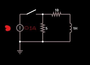
For reference, here is your circuit properly drawn with component designators:

The question is what happens when the inductor current starts at 0, then the switch is closed.

The first observation should be that the current source and the two resistors can be reduced to the equivalent Norton or Thevenin circuits. That is a current source with a single resistor in parallel, or a voltage source with a single resistor in series. The two are equivalent from the inductor's point of view. I'll pick the Thevenin version:

The current function should now be obvious from inspection because it's a simple L-R decay:

    I = Ifinal⋅(1 - e-t/Τ)

    I = (V1/R3)⋅(1 - e-t(R3/L1))

We can easily see that:

  • The initial current is 0.
  • The "final" current is V1/R3 = (5 V)/(15 Ω) = 333 mA.
  • The time constant is L1/R3 = (1 H)/(15 Ω) = 66.7 ms.

the time costant is L1/R so the t/T must have units of Ohms*seconds/Henries

I'm not sure what you are getting at. Resistance divided by inductance yields units of time. Specifically, Henrys / Ohms = seconds.

Ah, I just noticed that I accidentally flipped the time constant in the equation above. The exponential is supposed to be e-t/Τ, with Τ being L1/R3. I'll go fix that now.

History
Why does this post require moderator attention?
You might want to add some details to your flag.

2 comment threads

The original circuit is wrong. (3 comments)
Olin maybe you may want to delete this post. (3 comments)
Olin maybe you may want to delete this post.
MissMulan‭ wrote over 2 years ago

Olin maybe you may want to delete this post.

Olin Lathrop‭ wrote over 2 years ago

Why would I want to do that? As far as I can tell, it answers the question correctly. What do you think is wrong?

MissMulan‭ wrote over 2 years ago
  1. The current source provides 0.1A to the circuit but this could well have been a typo or you may have not seen it well which is partly my fault because I didnt write it brightly enough 2)the time costant is L1/R so the t/T must have units of Ohms*seconds/Henries