Change of pins in monostable multivibrator
In monostable multivibrators we use a trigger signal applied to the base of the transistor which is usually off to enter the astable region
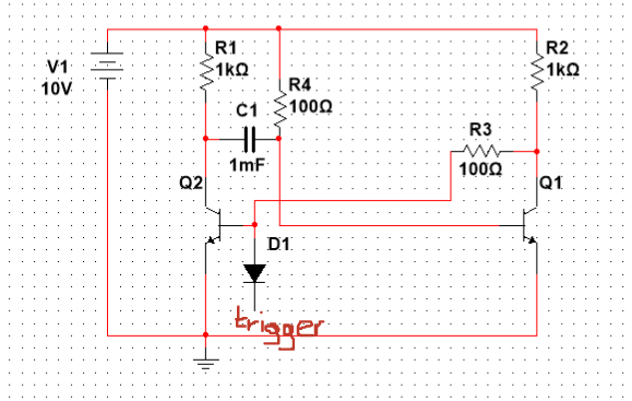
Can we instead have a pin which is connected directly to the base of Q1 and when that pin is grounded we will enter to the astable region?
2 answers
You are accessing this answer with a direct link, so it's being shown above all other answers regardless of its score. You can return to the normal view.
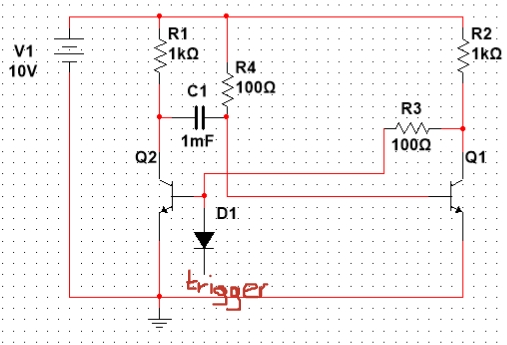
Your circuit will make sense if you do two things:
- significantly increase both R3 and R4
- reverse D1 or move it to Q1's base
Let's first see the role of the resistances R3 and R4.
These are base resistors; so their resistances should be higher than the collector resistances R1 and R2.
For example, Q1's base current is roughly IB1 = V1/R4 = 10/100 = 100 mA which is too much. R3 is a heavy load for the circuit output (the common point between R2 and Q1's collector) since R2 and R3 form a voltage divider with ratio of R3/(R2 + R3) = 0.1; so the output voltage will be only 1 V. Also, R3 would be a heavy load for the positive input voltage source connected to Q2's base (if you decide to control the circuit this way).
Let's now see what the role of the diode D1 is.
You can toggle this circuit in two ways - by applying a positive voltage to Q2's base (through a resistor) or by applying a zero voltage (ground) to Q1's base. In both cases, the role of the diode is to separate (if needed) the input voltage source from the circuit when its voltage is "inactive" (zero for the first case and high for the second case). So it should be backward biased in these cases - reversed in the first (OP's) case and connected in this direction in the second (Olin's) case.
If you toggle the circuit by a circuit with the so-called open collector output (a humble transistor), you do not need a diode since the driving circuit is disconnected when the transistor is off.
0 comment threads
The circuit you show doesn't make any sense:
Start by examining the steady state condition. In steady state, C1 is effectively an open, so you ignore it. R4 keeps Q1 on. That means the collector of Q1 will be low, which keeps the base of Q2 low, which means Q2 is off.
The diode doesn't do anything useful, and its cathode is certainly not a "trigger". Driving trigger high does nothing, since the diode is reverse biased. Driving trigger low only lowers the base of Q2 more. That still keeps Q2 off. Driving even lower will only exceed the reverse voltage capability of Q2's B-E junction, causing damage.
One way to trigger this one-shot would be to momentarily hold the base of Q1 low. That allows the collector of Q1 to go high, which turns on Q2, which causes the collector of Q2 to go low. C1 then provides a positive feedback path to continue keeping Q1 off. Eventually C1 charges up to the point where Q1 is no longer held off. Now there is positive feedback to flip Q1 on and Q2 off, ending the pulse. Since the circuit is stable in the Q1-on Q2-off state, it will remain that way until externally perturbed again.
0 comment threads

1 comment thread