Minimizing Common Mode Radiation - Separating Grounds
There are various different methods to keep common mode currents off the cables, one of them being discussed on the site here and with Olin's decoupling caps post on StackExchange. Slight digression - this is for some reason, extremely hard to comprehend to 9/10 engineers.
One of the approaches Henry Ott recommends in his Electromagnetic Compatibility Engineering (2009) is given on the image below:
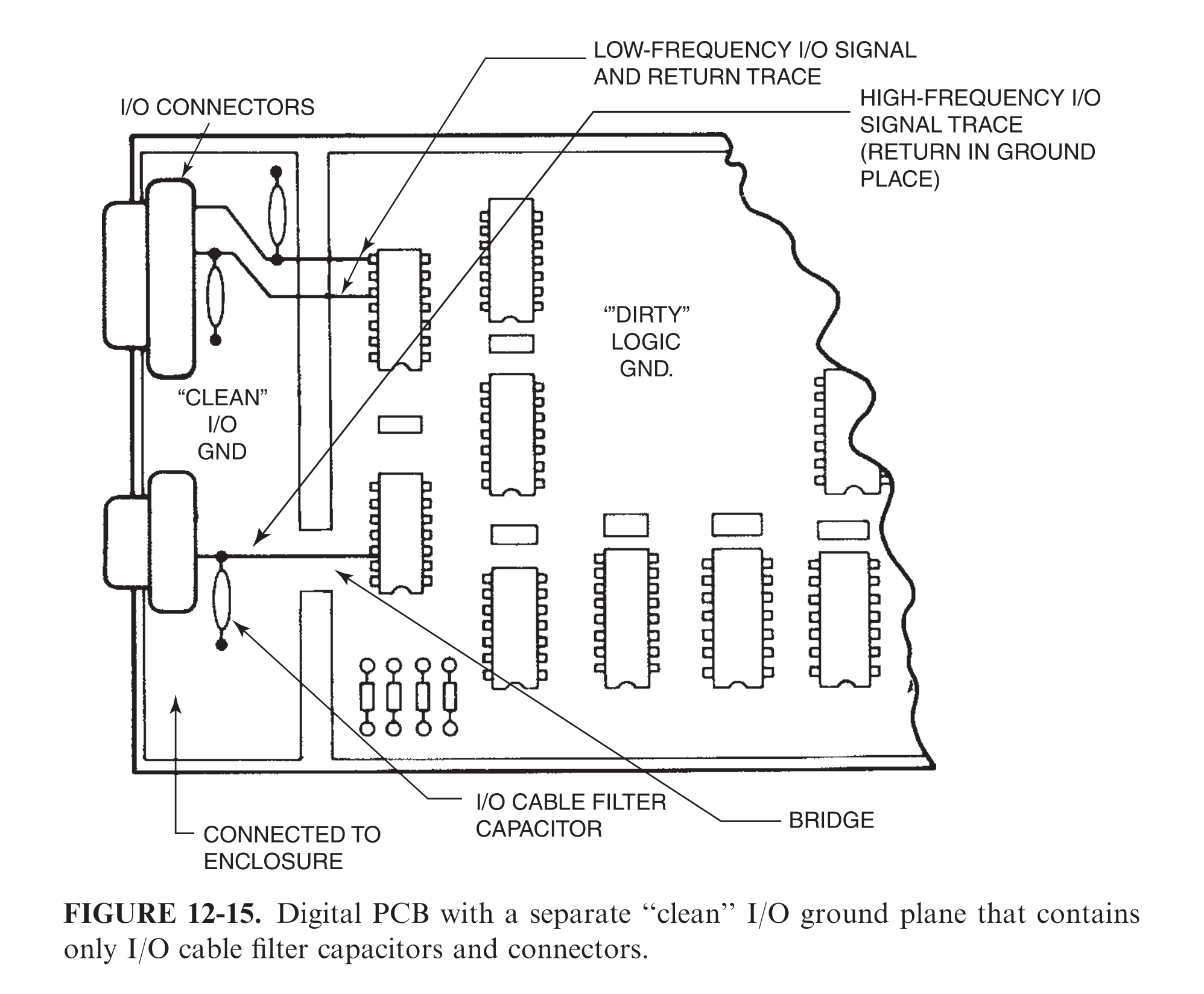
The dirty logic ground is something he describes as the ground where all IC's are connected - for example, all decoupling capacitors are directly punched to the GND plane, causing offset voltage which excites all cables attached to the board.
Therefore, to prevent this from happening, he then suggests all input cables be connected to something he calls "clean" I/O GND. This is the GND where the shield/metallic enclosure should be connected through a low-impedance connection as well.
High-speed signals(higher than 5-10MHz) going to connectors should be routed through the narrow plane bridge. Low-speed signals(lower than 5MHz) should be routed on top of the plane slot with the return signal being routed on the same layer next to it - companion trace being the return path rather than the plane.
Low impedance connection between clean ground and shield/enclosure is something he states is a clear must, due to obvious reasons. All traces shall as well be decoupled to the clean I/O GND using ceramic capacitors before leaving the board - this act as a shunt for all common mode ground current.
All clear for me so far, the part I don't get is:
- can this approach work in a plastic enclosure, without having the shield?
- how to correctly size and calculate the value of the capacitance? My gut feeling tells me around 100pF/0402 or similar small size/low inductance could do it
@AndyAka ... so, which is it; RF radiated emissions or cable-conducted emissions?
Potential failing of radiated emissions due to the ground plane offset voltage causing common-mode current to flow through the cables once when attached to the board. This would almost certainly mean conducted emission failure as well, but that is not the direct scope of the question.
@NickAlexeev...What type of high frequency signal have you got (frequency range differential or single-ended)? What kind of cable and connector have you got? Which EMC standard do you need to comply with (e.g. CISPR 11 class B) ?
The question was more conceptual - most of the devices I design don't end up in metallic enclosures and are almost always without shielded connectors. I don't go higher than ethernet or USB2.0 in terms of what ends up on cables - not on standard connectors --> product requirements. There is almost always a buck converter 20W-30W, switching in the 100kHz-1MHz range - even with only this on board, and a relatively low-speed differential bus(CAN at 100kBit) there could be a radiated emission issue after cables attached if the switcher layout is poor("dirty" loop currents flowing through the ground plane)
1 answer
The problem with cable emissions from HS data and SMPS noise is very common even with UTP and ribbon cable with adjacent grounds on differential signals.
I have seen this frequently on HDD testing at EMC sites, whereas the HDD emits nothing of interest. The problem is due to the imbalance of the cable single-ended to free-space relative to the drivers and receiver, while the differential impedance error is not a radiation factor. Thus the cable becomes an effective antenna per unit length. The best UTP twisted pairs or ribbon cable might be around 60 dB for imbalance to ground, even with adjacent gnd lines.
Remember "ground" is defined as your 0V reference, wherever that is, and in this case for EMI the detector antenna and Rx ground.
Unlike a laser-trimmed INA with 120 dB CMRR, the physical tolerances of insulation thickness and conductor thickness with skin depth are impossible to control to that equivalent of 1 ppm.
The choices are always;
- improve the CMRR balance, if possible.
- suppress the CM radiation with a single or double shield or CAT-5 STP cable.
- Raise the CM impedance sufficiently high with a balun or CM choke rated for at least 2 decades of f in the region of concern. This raises the impedance ratio to the shunt capacitance of the CM emissions with the shield capacitance in STP cable "ground". The shield termination important and as done in high speed Ethernet it is RC coupled with 75 ohms + 4.7 nF (?) to 0Vdc.
- For non-DC baseband data signals consider a Mag-jack PHY transformer which has the CM choke.
- Even SMT CM chokes for HDMI signals might be insufficient alone ( observed in ASUS designs.) improved with the shielding CM balun to add capacitance and bypass CM signals t local gnd.
If you have ever looked EEG or EKG designs you will notice they do not rely on the INA CMRR of 120 dB to reject line hum or other noise because of the imbalance of the cables and high CM noise of the subject. An additional 30 to 60dB CM rejection is done with filters.
- The CM choke solution is not limited to data but also the power interface cables.
simple Lab tests
Using a shorted loop scope probe is a good way to start sniffing for CM emission noise in the near-field noise. Then attach that to a spectrum analyzer and compare with the noise on your computer cables. You can also use a short piece of wire to scope probe or BMC T on a coax cable for an antenna for sniffing emissions. Of course, there are fancy probes, if you want to get calibrated E/H fields at a standard distance.
0 comment threads

3 comment threads