How to convert dv/dt of noise into frequency for filter capacitor selection?
Noise can be coupled between signal lines through parasitic capacitance formed between these signal lines, as
$i = C\frac{dv}{dt}$
where C is the capacitance between the signal lines.
Another way of noise coupling into signal lines is through inductive coupling, where changing magnetic field induces current into the adjacent signal line:
$v = L\frac{di}{dt}$
L being mutual inductance, and di being change of current in the aggressor line. To reduce noise sensitivity of the victim lines, capacitors can be placed on them, providing a low impedance return path. Capacitor impedance is frequency dependent, and effectively goes down up until the resonance frequency, at which point parasitic inductance becomes dominating, therefore it would be useful to pick a capacitor that has the lowest impedance at the frequencies present in the system.
However, it is the rate of change that causes the problem, so a 1kHz square wave with 10ps rise time could cause considerably more issues than a 1kHz square wave with 100us rise time.
Hence my question, if I know the rise times of certain signals in the system, how can I evaluate the frequency and therefore the appropriate type and value of capacitors to provide a low impedance path for a particular frequency?
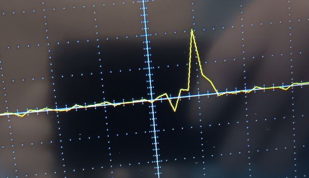
For example, if there is a recurring noise spike like this:
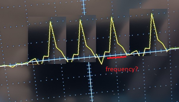
Would it be appropriate to imagine it as a periodic signal and see it as:
The importance of this can be seen as the rise times of integrated circuits are getting considerably faster as technology advances and dies are shrinking. Rick Hartley illustrated how closely coupled power and ground planes can provide low impedance path at frequencies where capacitors are no longer useful:
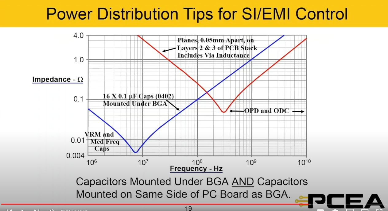
In the particular lecture it was in respect to power delivery, however, (I think) it also applies to noise filtering.
Any thoughts and suggestions are appreciated!
1 answer
It looks like you've sort of re-discovered a motivation for Fourier analysis. The difference between looking at slope versus frequency content is exactly the difference between time domain and frequency domain analysis. Both are perfectly valid and provide the same ultimate answers. However, one or the other is often more convenient and less work computationally. Often looking at the same issue both ways provides different insights. That may be the case here too.
You are right in that if you want to know the noise on a receiving line is bounded, you care about how the slew rate and amplitude of the transmitting line end up on the receiving line. That's all great until you look at capacitor datasheets and find their non-idea characteristics are specified as a function of frequency.
So how to relate the dV/dt you can measure to what the capacitor will do? First, in real-world circuit design we usually don't. I have never gotten into this level of detail to analyze coupled noise. I usually start with good design practices, good layout (quite important, often overlooked), try to squash nasty transients at their source, and general intuition. After that I build it an measure in the few rare cases where I suspect crosstalk might be a problem.
However, it sounds like your taking a class and need to do a theoretical analysis. In that case, the answer is Fourier analysis. Take one of the nasty spikes as you show in your first picture. Decide points where it starts and ends. Now generate the Fourier series for the interval. That pretends the signal repeats infinitely as in your second picture, although there is no need to ever consider that directly in the time domain.
Since you took the Fourier series of a fixed time interval, you end up with discrete sine at integer multiples of 1/period of the interval. For your purposes, you don't care about the relative phases. You now have a list of frequencies and their associated amplitudes.
For each frequency, you look at the capacitor datasheet to see how the cap works at that frequency. Use that to determine the overall attenuation of that frequency from the transmitting to the receiving line. Repeat for each frequency.
As you get higher in frequency, the amplitudes will generally decrease. At some point, you can ignore the frequencies because their amplitudes are so small that it wouldn't have a meaningful effect on the receiving line anyway.
One more thing I want to point out is that your first two equations don't actually tell you coupling attenuation directly. For example, the first one tells you how much current you get on the receiving line as a function of a voltage slope on the transmitting line. What you really want to know in most cases is how much voltage noise you get on the receiving line. That is a function of the induced current and the impedance of the receiving line. That's why a little capacitance on the receiving line helps, since that lowers its impedance at the high frequencies where noise coupling might be significant.
Now if you think about the above carefully, you notice that it's actually a rather long-about way to describe a capacitive voltage divider. Thinking of it that way can simplify things. If you think there is 5 pF coupling from the transmitting to the receiving line, and the receiving line has 100 pF of capacitance on it, then you can immediately see that to first approximation, fast edges will be attenuated by 21 times from transmitter to receiver. Then you look at the capacitor frequency characteristics and see if the capacitors will still be reasonably ideal at those frequencies.

0 comment threads